


LOCATION
The pump should ideally be placed as close as
possible to the liquid supply source. Allow sufficient
space on the sides and overhead to permit inspec-
tion and maintenance work to be performed.
FOUNDATION
The foundation for the pump should be level, pro-
vide rigid support and alignment of pump and
motor. It should also be of sufficient mass to
dampen any vibrations developed. Typically this is
accomplished by installing and grouting a Fybroc
baseplate on a concrete foundation.
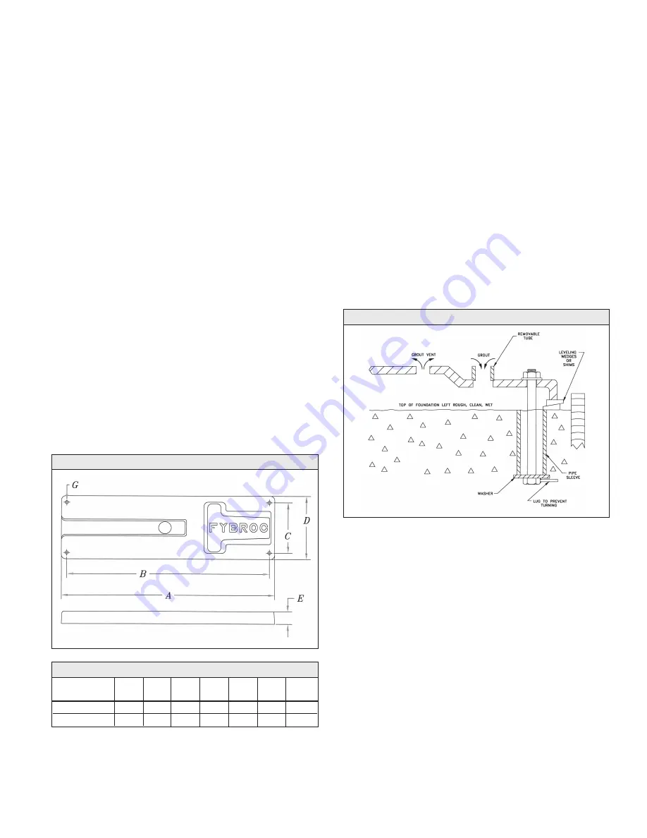
Foundation bolts of the proper size should be
imbedded in the concrete with anti-rotation lugs, lo-
cated by a drawing or template. (See Figure 1 and
Table 1 below for bolt-size and locations). A pipe
sleeve larger than the bolt should be used to allow
enough lateral movement for final positioning of the
bolts. (See Figure 2 below). Leveling wedges or
shims should be placed under the sides of the
baseplate to level the unit and the foundation bolts
slightly tightened.
A wood form can now be built around the edge of
the baseplate to contain the grout. The top of the
rough concrete foundation should be wetted down
prior to grouting. A good grade of non-shrinking
grout can now be poured through the fill hole on
the top of the fiberglass baseplate. On baseplates
with raised motor mounting sections, a short length
of pipe or tubing can be fitted into the grout hole to
allow the grout to completely fill the raised section
to the baseplate up to the vent hole in the raised
section, as shown in figure below. Once the grout
starts to set, the extension can be removed, leav-
ing the grout level with the top of the baseplate.
Once the grout has fully hardened, usually about
48 hours after pouring, the foundation bolts can be
fully tightened.
INITIAL ALIGNMENT
Final alignment of the pump and driver through the
flexible coupling is of extreme i mportance for
trouble free mechanical operation. If the driver was
mounted at the factory, the unit was rough aligned
with plastic shims prior to shipment. These shims
are not to be considered permanent and should be
replaced with metal shims during final alignment.
In addition, during transit and subsequent handling
any factory alignment may be disturbed. All units
must be re-aligned after installation and/or mainte-
nance.
The following steps are suggested to establish the
initial alignment of the pump unit:
1) Be sure the foundation bolts are tight.
2) Be sure the casing and frame feet are tight.
3) Use metal shims under the driver feet to
establish parallel and angular alignment of
pump and motor shafts.
FIGURE 2
INSTALLATION HORIZONTAL PUMPS
FIGURE 1
TABLE 1
Base A B C D E G Bolt
Plate Size
SP-1 50 47 1/2 12 15 2 7/8 3/4 1/2
SP-2 65 62 1/2 17 20 4 1 3/4
NOTE: Dimensions A & B are maximums and may be
less depending on pump/motor size.
4