Mestek TUBULAR GAS FIRED DIRECT SPARK PROPELLER UNIT HEATERS Installation Instructions And Parts Identification Download Page 19

19

OPERATION (continued) - PRIMARY AIR SHUTTER ADJUSTMENT

Primary air adjustment is made at the factory. No fi eld adjustments are necessary.

GAS INPUT RATE

2.  PROPANE GAS: An exact manifold pressure of 10.0 

inches WC (2.5 kPa) must be maintained for proper 
operation of the unit heater. If the unit is equipped 
with a pressure regulator on the combination gas 
valve, follow steps "a" through "d" above. If the unit 
is not so equipped, the propane gas supply system 
pressure must be regulated to attain this manifold 
operating pressure.

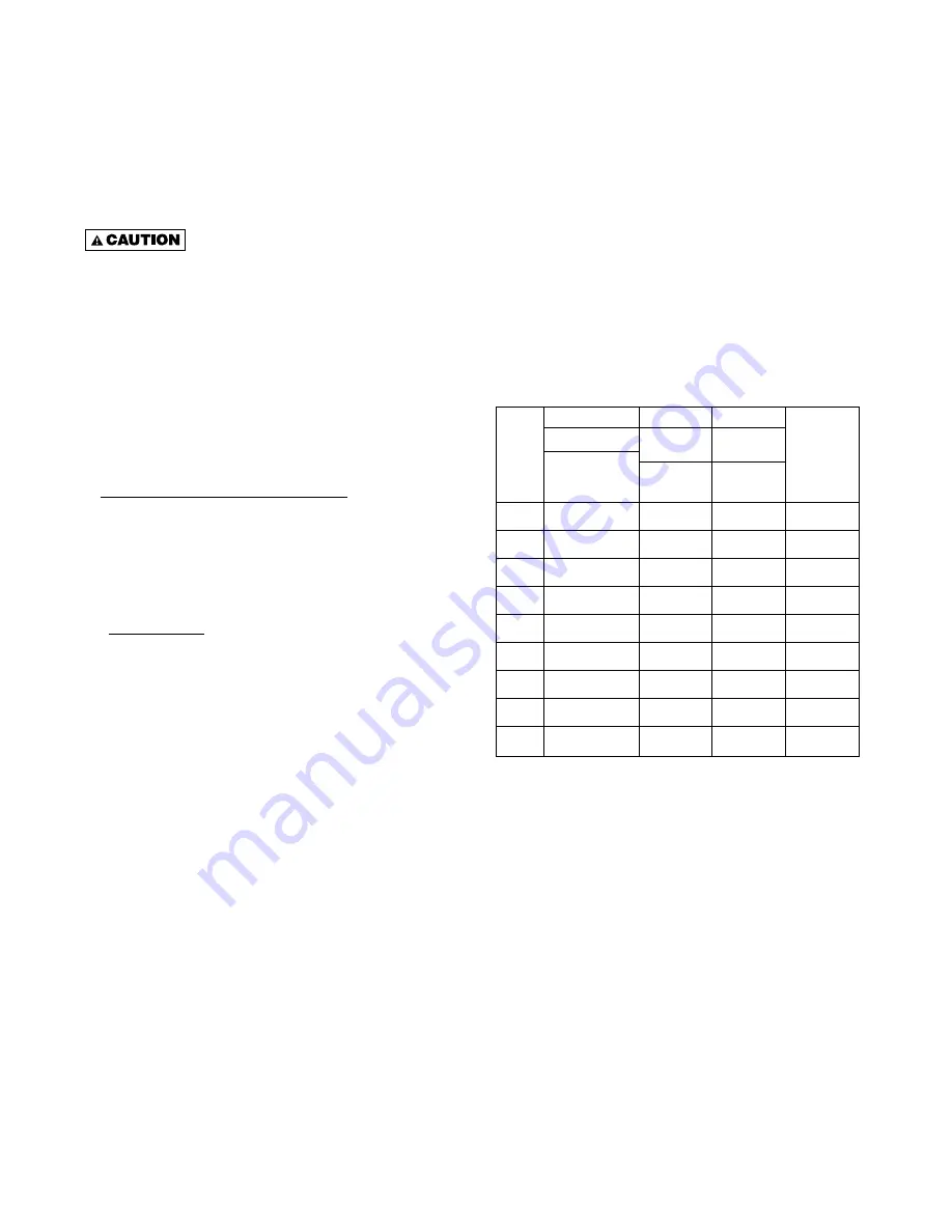
3.  The adjusted manifold pressure should not vary 

more than 10% from pressure specifi ed in Table 6.

Table 6 - Main Burner Orifi ce Schedule*

*

INPUT

IN 

1000

BTU

2500 BTU/Ft

3

(93.1 MJ/m

3

)

PROPANE

TYPE OF GAS

NATURAL

HEATING VALUE

1050 BTU/Ft

3

(39.1 MJ/m

3

)

3.5 INCH WC

(0.87kPA)

10 INCH WC

(2.49 kPA)

NUMBER

OF BURNER

ORIFICES

MANIFOLD

PRESSURE

4

5

6

7

8

9

10

11

12

100

125

150

175

200

250

300

350

400

FT 

3

/HR

ORIFICE DRILL

FT 

3

/HR

ORIFICE DRILL

FT 

3

/HR

ORIFICE DRILL

FT 

3

/HR

ORIFICE DRILL

FT 

3

/HR

ORIFICE DRILL

FT 

3

/HR

ORIFICE DRILL

FT 

3

/HR

ORIFICE DRILL

FT 

3

/HR

ORIFICE DRILL

FT 

3

/HR

ORIFICE DRILL

93
42

116

42

140

42

163

42

186

42

233

42

280

42

326

42

372

42

40
53
50
53
60
53
70
53
80
53

100

53

120

53

140

53

160

53

*This schedule is for units at operating at normal altitudes of 2000 feet 
(610m) or less.

When installed in Canada, any references to deration at altitudes in excess of 
2000 feet (610m) are to be ignored. At altitudes of 2000 to 4500 feet (610 to 
1372m), the unit heaters must be fi eld derated to 90% of the normal altitude 
rating, and be so marked in accordance with ETL certifi cation. See Table 6A 
for fi eld deration information.

Check the gas input rate as follows (Refer to General 
Safety Information section for metric conversions).

 Never overfi re the unit heater, as this 

may cause unsatisfactory operation, or shorten the 
life of the heater.

1.  Turn off all gas appliances that use gas through the 

same meter as the unit heater.

2.  Turn the gas on to the unit heater.
3.  Clock the time in seconds required to burn 1 cubic 

foot of gas by checking the gas meter.

4.  Insert the time required to burn one cubic foot of 

gas into the following formula and compute the input 
rate.

    3600 (Sec. per Hr.) X BTU/Cu. Feet    


           = Input Rate


Time 

(Sec.)

For example:
Assume the BTU content of one cubic foot of gas is 
1000, and that it takes 18 seconds to burn one cubic 
foot of gas.
 

3600  x 1000  


                       =  200,000


   18

NOTICE: If the computation exceeds, or is less than 
95% of the gas BTU/hr. input rating (see Table 5), 
adjust the gas pressure.

Adjust the gas pressure as follows:

1.  NATURAL GAS: Best results are obtained when 

the unit heater is operating at its full rated input with 
the manifold pressure of 3.5 inches WC (0.9 kPa). 
Adjustment of the pressure regulator is not normally 
necessary since it is preset at the factory. However, 
fi eld adjustment may be made as follows:
a.  Attach manometer at the pressure tap plug 

adjacent to the control outlet.

b.  Remove the regulator adjustment screw cap, 

located on the combination gas valve.

c.  With a small screwdriver, rotate the adjustment 

screw counterclockwise to decrease pressure, or 
clockwise to increase pressure.

d.  Replace regulator adjustment screw cap.

Summary of Contents for TUBULAR GAS FIRED DIRECT SPARK PROPELLER UNIT HEATERS

Page 1: ...t any problem that may be found RECEIVING INSTRUCTIONS Inspect shipment immediately when received to determine if any damage has occurred to the unit during shipment After the unit has been uncrated c...

Page 2: ...on Air 5 7 Proper Clearances 5 7 Suspension of Units 5 7 Heat Throw Data 6 Gas Piping 8 9 ELECTRICAL CONNECTIONS 10 11 12 VENTING 13 14 15 16 17 OPERATION Explanation of Controls and Operation 18 Main...

Page 3: ...t Start Up Sheet located in this manual Use only the fuel for which the heater is designed see rating plate Using LP gas in a heater that requires natural gas or vice versa will create risk of gas lea...

Page 4: ...9 279 311 311 311 E Hanging Distance Width 18 5 8 18 5 8 18 5 8 30 5 8 30 5 8 30 5 8 48 5 8 48 5 8 48 5 8 473 473 473 778 778 778 1235 1235 1235 F Discharge Opening Width 18 3 4 18 3 4 18 3 4 30 3 4 3...

Page 5: ...ve the floor must be equipped with an OSHA approved fan guard Refer to the latest edition of NFPA 88A Parking structures In Canada installation must be in accordance to the latest edition of CSA B149...

Page 6: ...NR NR 44 47 58 66 71 75 6 1 13 4 14 3 17 7 20 1 21 6 22 9 60 8 75 80 85 90 95 110 125 130 138 2 4 22 9 24 4 25 9 27 4 29 0 33 5 38 1 39 6 42 1 10 65 70 75 79 83 95 109 115 120 3 0 19 8 21 3 22 9 24 1...

Page 7: ...ere is a possibility of distortion or discoloration of adjacent materials Make certain that the lifting methods used to lift the heater and the method of suspension used in the field installation of t...

Page 8: ...vity Gas Nominal Iron Internal Length of Pipe Feet meters Pipe Size Diameter 10 20 30 40 50 60 70 80 90 100 125 150 175 200 Inch Inch 3 0 6 1 9 1 12 2 15 2 18 3 21 3 24 4 27 4 30 5 38 1 45 7 53 3 61 0...

Page 9: ...al Fuel Gas Code in Canada according to CSA B149 See Tables 1 3 for correct gas piping size If gas pressure is excessive on natural gas applications install a pressure regulating valve in the line ups...

Page 10: ...tical vibration free surface free from air currents and in accordance with the furnished instructions Mount the thermostat approximately 5 feet 1 5m above the floor in an area where it will be exposed...

Page 11: ...11 ELECTRICAL CONNECTIONS continued Figure 5d Tubular Units Equipped with Natural Gas and Propane LP Gas...

Page 12: ...12 ELECTRICAL CONNECTIONS continued Figure 5e Tubular Unit Sizes with Optional 2 Stage Ignition...

Page 13: ...operating the gas unit heater will result in the spillage of flue gas into the occupied space 9 Avoid installing units in areas under negative pressure due to large exhaust fans or air conditioning W...

Page 14: ...isance or hazard or could be detrimental to the operation of regulators relief valves or other equipment The vent pipe equivalent length must not exceed 50 feet 15 2m Equivalent length is the total le...

Page 15: ...r in the absence of local codes with current CSA B149 1 Installation Codes for Natural Gas Burning Appliances and Equipment or CSA B149 2 Installation Codes for Propane Gas Burning Appliances and Equi...

Page 16: ...16 Figure 8A Figure 8B VENTING continued D3620F D3619C...

Page 17: ...17 VENTING continued Figure 9A Figure 9B D3661F D3662D...

Page 18: ...motor is de energized 6 The fan operation is delayed 30 seconds once the thermostat is closed and continues operation for 30 seconds after the thermostat opens NOTICE The start up fan delay must not e...

Page 19: ...eaters must be field derated to 90 of the normal altitude rating and be so marked in accordance with ETL certification See Table 6A for field deration information Check the gas input rate as follows R...

Page 20: ...Refer to Installation Instruction section on Adjustments Gas Input Rate for adjusting the manifold pressure Manifold Pressure Inc WC PROPANE LP GAS NATURAL GAS Heating Value BTU Hr Altitude Feet 8 6...

Page 21: ...t openings 3 Clean heat exchanger Refer to Installation 4 Determine cause and repair accordingly 1 Inspect all gas piping and repair 2 Check to ensure gas test ports are seated 3 Clean heat exchanger...

Page 22: ...tat 1 Replace or tighten 2 Clean power ventor wheel 3 Realign power ventor wheel 1 Check and tighten wires on fan circuit 2 Test for 115v on terminal ACB Heat and L2 if voltage is present replace moto...

Page 23: ...heat If not present and all checks are normal replace 1 Check power ventor circuit per wiring diagram 2 Check motor voltage and amp draw to motor name plate replace if motor found defective 3 Check f...

Page 24: ...er 3 5 Amp fuse on circuit board 1 Common side of transformer grounded to chassis 2 Loose spark ignitor 1 Gas supply off or gas supply pressure too low 2 Flame sense rod contaminated or loose wire 3 G...

Page 25: ...supplied with your unit NOTICE The heater and vent system should be checked once a year by a qualified technician All Maintenance Service information should be recorded accordingly on the Inspection...

Page 26: ...ing halogenated hydrocarbons precipitated in the air d to any workmanship of the installer of the Product 3 This limited warranty is conditional upon a advising the installing contractor who in turn n...

Page 27: ...ICATION OF PARTS PROPELLER UNIT HEATERS Figure 13 Heat Exchanger Assembly Figure 14 Electrical Control Panel Figure 11 Propeller Parts Figure 12 Component Parts D4430 Fan Guard Fan Blade Hardware Hard...

Page 28: ...Venter Assembly 300 400 Unit Sizes Shown HOW TO ORDER REPLACEMENT PARTS Please send the following information to your local representative if further assistance is needed contact the manufacturer s cu...

Page 29: ...29 NOTES...

Page 30: ...30 NOTES...

Page 31: ...11 Supply Voltage SV 1 115 1 60 5 230 3 60 2 208 1 60 6 460 3 60 3 230 1 60 7 575 3 60 4 208 3 60 Z Other Note Supply Voltage SV 2 7 include field mounted step down transformer 12 Motor Type MT 1 Ope...

Page 32: ...s equipment unless you fully understand the controls GAS EQUIPMENT START UP GENERAL With power and gas off Make certain all packing has been removed Tighten all electrical terminals and connections Ch...

Reviews: