Form 43343350
-44-
Dec 2017
8.
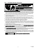
Single-wall metal pipe shall not originate in any unoccupied attic or concealed space and shall not pass
through any attic, inside wall or concealed space, or through any floor. For the installation of a single-wall
metal pipe through an exterior combustible wall, refer to latest edition of the National Fuel Gas Code or the
authority having jurisdiction.
9.
A venting system shall terminate at least 3 ft. above any forced air inlet located within 10 ft.
SINGLE HEATER VENTING (HORIZONTAL THROUGH SIDEWALL)
When venting the heater horizontally through a combustible outside sidewall, the same requirements listed
previously for venting Vertical Through The Roof apply except as follows:
1.
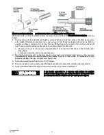
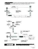
A vent passing through a combustible wall must pass through an approved clearance thimble (Air-Jet #4VT
or Ameri-Vent #4EWT or other thimbles) that are listed by a nationally recognized testing agency; double
wall Type B vent must be used for the portion of the vent system which passes through the combustible
sidewall.
2.
An approved vent cap (Breidert or equal) must be attached to the end of the vent pipe.
NOTE: To minimize problems associated with condensation in long horizontal runs, vent pipe can be insulated.
3.
Use the following correction factors to obtain the equivalent length when elbows are used:
Subtract 10 ft. for each elbow beyond 15 ft. from the heater.
Subtract 15 ft. for each elbow within 15 ft. of the heater.
4.
Limit to (2) 90º elbows in the vent system.
5.
When venting through a sidewall, the horizontal vent pipe shall fall 1/4 inch per 10 feet down from the start
of the vent system to the vent terminal. All portions of the vent pipe shall be supported to prevent sagging.
(6’ spacing is recommended)
6.
A minimum clearance of 6 inches must be maintained between the outside wall and vent cap (18”
clearance will provide stability under high wind conditions).
7.
The horizontal venting system shall not terminate:
Less than 4 ft. (1.2m) below, 4 ft. (1.2m) horizontally from or 1 ft. (30cm) above any door, operable
window or gravity air inlet into any building. The bottom of the vent terminal shall be located at least 7
ft. (2.1m) above grade or above snow accumulation level as determined by local codes.
Less than 3 ft. (0.9m) from a combustion air inlet.
Less than 3 ft. (0.9m) from any other building opening or any gas service regulator.
Less than 7 ft. (2.1m) above public walkways.
Directly over areas where condensate or vapor could create a nuisance or hazard or be harmful to the
operation of gas utility meters, regulators, relief valves, or other equipment. Building materials should
be protected from flue gases and condensate.
Less than 18” (0.45m) when directly below a combustible overhang.
8.
In regions of the country where prevailing winds are consistently higher than 40 mph, it may be necessary to
terminate the vent system above the roof level.
Summary of Contents for 44488010
Page 15: ...Form 43343350 14 Dec 2017 7 1 TYPICAL ASSEMBLY LAYOUT STRAIGHT SERIES SHOWN ...
Page 16: ...Form 43343350 Dec 2017 15 8 0 DIMENSIONS STRAIGHT SERIES Typical Dimensions Up to 60 Ft Shown ...
Page 17: ...Form 43343350 16 Dec 2017 8 1 DIMENSIONS U SERIES Typical Dimensions Up to 50 Ft Shown ...
Page 18: ...Form 43343350 Dec 2017 17 8 2 HEATER ASSEMBLY JOINING OF TUBE SECTIONS ...
Page 19: ...Form 43343350 18 Dec 2017 ...
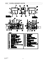
Page 52: ...Form 43343350 Dec 2017 51 20 0 CONTROL COMPONENT LOCATION ...
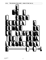
Page 54: ...Form 43343350 Dec 2017 53 22 0 TROUBLESHOOTING GUIDE SINGLE STAGE N1 L1 ...
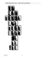
Page 55: ...Form 43343350 54 Dec 2017 TROUBLESHOOTING GUIDE SINGLE STAGE CONTINUED ...
Page 56: ...Form 43343350 Dec 2017 55 TROUBLESHOOTING GUIDE SINGLE STAGE CONTINUED ...
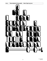
Page 57: ...Form 43343350 56 Dec 2017 22 1 TROUBLESHOOTING GUIDE TWO STAGE N2 L2 ...
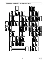
Page 58: ...Form 43343350 Dec 2017 57 TROUBLESHOOTING GUIDE TWO STAGE CONTINUED ...
Page 59: ...Form 43343350 58 Dec 2017 TROUBLESHOOTING GUIDE TWO STAGE CONTINUED ...
Page 66: ...Form 43343350 Dec 2017 65 ...


