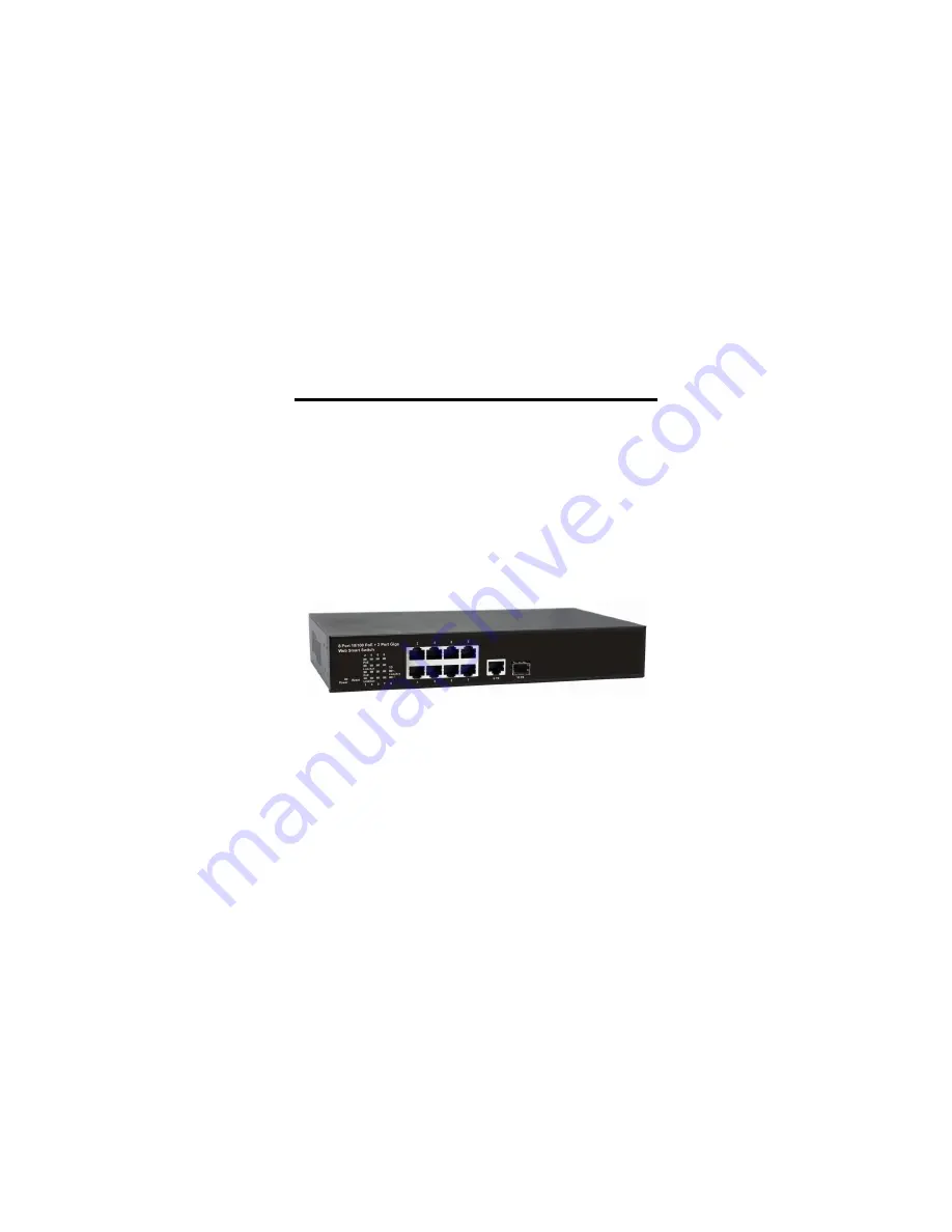
8-Port 10M/100M + 2-Port Giga (1GT+1G SFP)
Web Managed PoE Switch
User Manual
20130
9
.008
.
A1
Page 1: ...8 Port 10M 100M 2 Port Giga 1GT 1G SFP Web Managed PoE Switch User Manual 201309 008 A1...
Page 2: ...occur in a particular installation If this equipment does cause harmful interference to radio or television reception which can be determined by turning the equipment off and on the user is encourage...
Page 3: ...Authentication Configuration 12 4 2 2 System IP Configuration 12 4 2 3 System Status 14 4 2 4 Load Default Setting 15 4 2 5 Firmware Update 16 4 3 Port Management 18 4 3 1 Port Configuration 18 4 3 2...
Page 4: ...5 4 7 2 TCP UDP Filter 36 4 8 Spanning Tree 38 4 8 1 STP Bridge Settings 38 4 8 2 STP Port Settings 39 4 8 3 Loopback Detection Settings 40 4 9 Trunking 42 4 10 Backup Recovery 44 4 11 Miscellaneous 4...
Page 5: ...is designed for small or medium network environment to strengthen its network connection This product is compact 11 size making it ideal for Desktop users with limited space It also gives you the opti...
Page 6: ...th Control Up to 256 levels Bandwidth Control for TX and RX Rate Broadcast Storm Control Broadcast Storm Control and Threshold Setting PoE Control PoE Enable Disable PoE Status Port Counter Statistic...
Page 7: ...ort 10 can be aggregated LACP Long Short Timeout time IGMP Snooping V1 V2 Basic Features Embedded HTTP web Management User name Password Authentication Configuration Configuration Backup Recovery TFTP...
Page 8: ...3 Package Before you start to install this switch please verify your package that contains the following items One Switch One Power Cord One User Manual CD Optional Accessory 11 to 19 Rack mount kit...
Page 9: ...sts of 8 10 100Base TX RJ 45 ports 1 10 100 1000M RJ 45 and 1 Gigabit SFP uplink ports LED The LED Indicators are also located on the front panel They indicate the System and Port Status Load Default...
Page 10: ...ower socket close by The flat space should be clean smooth level and sturdy Make sure there is enough clearance around the switch to allow attachment of cables power cord and allow air circulation The...
Page 11: ...her is RX receive Cross connect the transmit channel at each end to the receive channel at the opposite end 2 4 Hardware Restore Button The purpose of this button is to provide a method for the networ...
Page 12: ...n your network and that every PC on this network can access the switch via the web browser Verify that your network interface card NIC is operational and that your operating system supports TCP IP pro...
Page 13: ...efault user name and password are both admin If you can t login the switch the following steps can help you to identify the problem 1 Switch to DOS command mode and type the ipconfig to check the NIC...
Page 14: ...ure At the first open the web browser and go to 192 168 2 1 site then the user will see the login screen Key in the password to pass the authentication then clicks the OK The log in process is complet...
Page 15: ...Main Page Figure 1 3 11...
Page 16: ...nd Password in this page Figure 2 1 12 13 3 System IP Configuration This page shows system configuration including the current IP address Subnet Mask and Gateway Figure 2 2 User can configure the IP s...
Page 17: ...ch will try get the IP Address from the DHCP server Click Update to update the new settings It will show update successfully then press Reboot button It will enter user login screen automatically Clic...
Page 18: ...address assigned by manufacturer default Number of Ports Displays number of ports in the switch Comment Add character here for not System Version Displays the switch s firmware version Idle Time Secur...
Page 19: ...following The purpose of this button is to provide a method for the network administrator to restore all configurations to the default value To activate this function the user should follow the follow...
Page 20: ...e of flash memory will be erased All functions will be detected except the firmware update itself If want proceed click Yes to continue If not please click Cancel Figure 2 6 The smart switch will eras...
Page 21: ...ht of the Browse command will display the file name you selected Press Update to continue the firmware upgrading process Figure 2 8 The below screen shows the Uploading process is starting Figure 2 9...
Page 22: ...on Function Tx Rx Ability Enable or Disable The default value is Enable Being set as Enable the port can Transmit and Receive packet without any problem After changed to Disable the selected ports can...
Page 23: ...re Flow Control for connection at speed of 10 100Mbps in Half duplex mode Addr Learning When the Auto Negotiation column is set as Disable users have to set this column as Enable or Disable Select Por...
Page 24: ...what type of packet is to be monitored Rx indicates the Received Packets Tx indicates the Transmitted Packets Tx Rx indicates Both Transmit and Received Source Port The ports that the user wants to mo...
Page 25: ...5 for both Tx and Rx Rate and select the High as speed base for port 1 and port 10 The actual rate for port 1 Fast Ethernet is 1280 for port 9 Gigabit Port is 10240 You could see the table is updated...
Page 26: ...ge and also enable or disable per port time unit The one time unit is 50us for Gigabit speed 500 us for 100Mbps speed and 5000us for 10Mbps speed The excessive broadcast packet will be discarded For t...
Page 27: ...Port The port number Enable Enable PoE feature of the specific ports PSE Current The PSE Current Range Minimum Output Power The minimum output power of the port PoE Class The PoE class of the connect...
Page 28: ...switch physically 12 13 3 VLAN Mode You may select the VLAN Mode of the switch Port based VLAN is for separating traffic only on this single switch There is no handover of network traffic within VLAN...
Page 29: ...eived at the source port This is the default setting when starting VLAN configuration You should change to either Add or Remove Tag Remove Tag Remove tag means the 802 1Q tag of the outgoing packet of...
Page 30: ...ect or deselect the ports that are on the same VLAN group In this configuration mode you do not need to worry about defining VLAN groups and VLAN IDs VLAN Member in Tag Based Mode In Tag Based Mode yo...
Page 31: ...r for this entry and then press this button to add a VLAN entry to the table The available range of VID is from 1 4094 Delete Select a VID in the table and then press this button to remove a VID entry...
Page 32: ...ged the incoming packets will then be tagged with PVID within the switch and then follow the VID table to forward traffic Port VID Map This table shows the PVID of the ports VLAN Member Table This tab...
Page 33: ...etting Multi to 1 VLAN is used in CPE side of Ethernet to the Home and is exclusive to VLAN setting on VLAN Member Setting When VLAN member Setting is updated multi to 1 setting will be void and vice...
Page 34: ...count Collision Count Transmit packet This category shows the packets outgoing from the switch and the count of collision Drop packet Receive packet This category shows the number of received valid p...
Page 35: ...Clear Press clear will clear all counters Refresh Press Refresh button will aggregate the number of the counter for all ports 31...
Page 36: ...asses but they do not guarantee delivery as do quality of service QoS functions which are implemented in the network devices 12 13 3 Priority Mode There are three priority modes available to specify t...
Page 37: ...et received by a high priority port is handled as a high priority packet VLAN Tag The switch follows the VLAN tag of the incoming packets to forward traffic VLAN Tag priority high priority 4 7 low pri...
Page 38: ...dministrator to assign the specific application to a priority queue F I F O The incoming packet will be forwarded in first in first out scheme Discard The incoming packet will be discarded at the sour...
Page 39: ...specific port Figure 7 1 MAC Address Type the target MAC address you want to bind for the specific port User can assign up to 3 MAC addresses to the port Select Port Select the port number and click...
Page 40: ...ped and other d protocol will be forwarded and other ed known protocol or User_Define Protocol AN Port The port number of the Secured WAN Port The Port Filtering Rule The outgoing packet with selec ei...
Page 41: ...Click Update to have the configuration take effect 37...
Page 42: ...eter configures the spanning tree priority globally for this switch The device with the highest priority becomes the STP root device However if all devices have the same priority the device with the l...
Page 43: ...shows the STP configuration of the switch The Root Status shows the Root Switch s Information of the STP domain 12 13 3 STP Port Settings The STP Port Setting page allows you to change the port prior...
Page 44: ...ports with slower media Set the RSTP path cost on the port Number between 0 200000000 0 means auto generated path cost State Show the current port state includes Designated port Root port or Blocked p...
Page 45: ...Detection function Auto Wake Up Once the Loopback Detection function is running the ports maybe be disabled to avoid the loop The Auto Wake Up allows you to activate the port after Time Interval passe...
Page 46: ...is maintained whenever a link in a trunk is lost or returned to service This switch may use Source MAC Address or a combination of Source MAC Address and Destination MAC Address to be the selection f...
Page 47: ...tion Key This column allows you to type operation key Time Out This column allows you to select Long Time Out Time or Short Time Out Time The Long Time Out is around 30 seconds the Short Time Out is a...
Page 48: ...nfiguration The user can save configuration file to a specified file If the user wants to recover the original configuration which is saved at the specified path just enter the password and then press...
Page 49: ...multicast stream is continuously generating from the source port the client port may be congested because of the limited bandwidth or slow network processing ability Then the Pause frame of Flow Contr...
Page 50: ...n cause unnecessary load on host devices by requiring them to process packets they have not solicited The IGMP snooping is a feature that allows the switch to listen in on the IGMP conversation betwee...
Page 51: ...N uplink function is enabled and the destination port of an unicast packet is located at the next VLAN this packet will be forwarded to the uplink port Choose the Uplink Port X for the port ID The Upl...
Page 52: ...ch you can click Logout to leave the configuration page The administrator has write access for all parameters governing the onboard agent User should therefore assign a new administrator password as s...
Page 53: ...Step 1 Turn on the Web Smart Switch Step 2 Press and hold the reset button continuously for 5 seconds and release the reset button Step 3 The switch will reboot for 20 seconds and the configuration o...
Page 54: ...rst Release Nov 15 2012 V1 1 Update latest product specification Update latest figure of web UI Add information of the Miscellaneous setting Jan 9 2013 V1 2 updated Optional Accessory 11 to 19 Rack mo...