www.messko.com
Affi
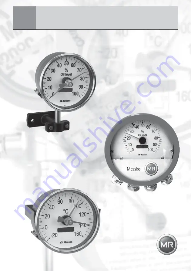
cheur electronique/electronic indicator
Manuel d’utilisation/Operating Instructions
EI100EI100/160
BA 2053/08/18: français english
Messko
Page 1: ...www messko com Afficheur electronique electronic indicator Manuel d utilisation Operating Instructions EI100 EI100 160 BA 2053 08 18 français english Messko ...
Page 2: ...BA 2053 08 18 2 ...
Page 3: ...manuel pour utilisation future Contents 1 Safety 4 1 1 Safety instructions 4 1 2 Specified application 4 1 3 Important notes on equipment operation 4 2 Product specification 5 3 Installation 6 4 Electrical connection 6 4 1 Power supply 24VDC 6 4 2 Sensor signal 4 20mA 6 5 Function test 8 6 Technical data 8 7 Installation diagram 9 7 1 EI100 on stand 9 7 2 EI100 with clamp strap 10 7 3 EI100 160 10...
Page 4: ...nal health safety regulations It is especially emphasized that tasks performed on live i e dangerous contact components are permissible only while these components are either de energized or protected against direct contact 1 2 Application Le EI100 ou EI100 160 permet l indication à distance de la température au travers d une information analogique prove nant d un capteur En complément de l affich...
Page 5: ...age ou en degré centigrade selon l application Electrical installation is subject to the relevant national safety regulations It is imperative to connect the protective conductor in order to ensure trouble free operation 2 Product specification The remote electronic indicator El100 or EI100 160 shows the temperature or a modulation in percent of any desired sensor This is indicated by an analog po...
Page 6: ...o connect the 4 20mA signal of the sensor I1 Passive sensor without own power supply I2 Active sensor or active 4 20mA current circuit With both types of connection remember the maximum load of the sensor Sensor input I1 passiv The passive input delivers a voltage of 24 VDC Connect the lines as shown in the circuit diagram figure 5 EI100 or figure 6 EI100 160 to the and terminals ATTENTION Les con...
Page 7: ...ique El 100 20 140 C 4 20mA Examples of passive sensors A Oil temperature Thermometer MT ST 160 SK TT or combi sleeve TT See current circuit diagram 8 1 page 11 B Winding temperature Thermometer MT ST 160W TTor ZT F2 TT See current circuit diagram 8 2 page 12 Sensor input I2 active Connect the lines as shown in the circuit diagram figure 5 EI100 or figure 6 EI100 160 to the and terminals Examples ...
Page 8: ...raîchissement 20ms Chute de tension max 50mV à l entrée de mesure Alimentation Alimentation UV ca 3V du capteur pour l entrée capteur passif 5 Function test Check the electrical connection of the El 100 or EI100 160 using the circuit diagram in chapter 8 Switch on the power supply The value shown must correspond to the value of the sensor Take the tolerances from the data sheets of the equipment t...
Page 9: ...pacity VDE 0435 part 303 Short term current VDE 0435 part 303 Fault stability impulses IEC 61000 4 4 Fault stability HF IEC 61000 4 6 Fault stability discharge IEC 61000 4 2 Fault stability power cut IEC 61000 4 11 Fault stability surge IEC 61000 4 5 Fault stability magnetic fields IEC 61000 4 8 Cold IEC 60068 2 1 Dry Heat IEC 60068 2 2 Damp Heat constant IEC 60068 2 3 Damp Heat cyclical IEC 60068...
Page 10: ...ille Pointer Ajustement aiguille entraînée Adjustment for maximum pointer Aiguille entraînée Maximum pointer Capot de protection des bornes Clamp cover Presse étoupe M20x1 5 selon EN 60423 Cable gland M20x1 5 selon EN 60423 Aiguille Pointer Capot de protection de bornes Terminal cover Plaque de montage Mounting plate Presse étoupe M20x1 5 Manifold for cable gland M20x1 5 Version standard M25 x 1 5...
Page 11: ... 18 Messko 11 8 Schémas de cablâge Circuit diagrams 8 Schémas de cablâge 8 1 Température de l huile capteur passif 8 Circuit diagrams 8 1 Oil temperature passive sensor 24VDC 4 20mA R I I1 I 2 R I ϑ Fig 10 Fig 10 ...
Page 12: ... 2053 08 18 12 8 Schémas de cablâge Circuit diagrams 8 2 Température d enroulement capteur passif 8 2 Winding temperature passive sensor Fig 11 Fig 11 Ω Ω Ω Ω Ω Ω Ω Ω Ω Ω Ω Ω Ω 24VDC 4 20mA R I I1 I 2 R I ...
Page 13: ... actif Fig 12 Fig 12 8 Schémas de cablâge Circuit diagrams 24VDC 4 20mA R I I1 I 2 R I Messko 2 1 3 4 6 5 TRIP ERROR POWER ALARM S 4 S 3 S 2 S 1 22 21 23 24 25 13 7 8 11 9 10 12 16 15 14 18 17 19 20 EPT 202 35 30 28 27 26 29 31 32 33 34 37 36 39 38 40 41 42 43 ...
Page 14: ...roulement capteur actif 8 4 Winding temperature active sensor Fig 13 Fig 13 36 39 38 40 41 42 43 24VDC 4 20mA R I I1 I 2 R I Messko 2 1 3 4 6 5 TRIP ERROR POWER ALARM S 4 S 3 S 2 S 1 22 21 23 24 25 13 7 8 11 9 10 12 16 15 14 18 17 19 20 EPT 202 35 30 28 27 26 29 31 32 33 34 37 ...
Page 15: ...BA 2053 08 18 Messko 15 Fig 14 Fig 14 8 Schémas de cablâge Circuit diagrams 8 5 Température de l huile capteur actif 8 5 Oil level active sensor ...
Page 16: ...ed in all of our publications may differ in detail from the actual equipment delivered We reserve the right to make alterations without notice BA2053 08 18 0411 Art aucune Art no 76921100 Printed in Germany Messko GmbH 2011 Messko www messko com Messko GmbH Phone 49 0 6171 6398 0 Gewerbegebiet An den Drei Hasen Fax 49 0 6171 6398 98 Messko Platz 1 E Mail info messko com D 61440 Oberursel Taunus In...