background image


42 


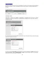
The Event List is allowed to add up to 3 event handling illustrated as below. It is the summary of all 


configured event details.   

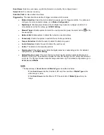
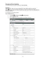
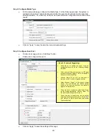
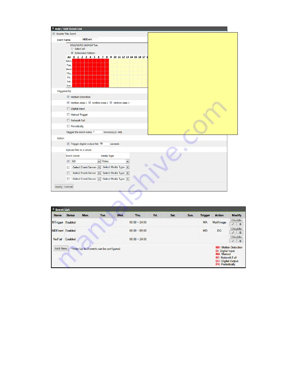
- Event of Motion Detection - 

 
a. 

Check the box to enable this event.  

 
b. 

Give a name of this event setting; e.g. MD Event 
(stands for Motion Detection). This is an identity 
of an object of event handling.  

 
c. 

Select time frame in the schedule table, for the 
requirement that is available from 00:00 to 08:00 
every day. 


d. 

Select “Motion Detection” for this event’s trigger 
source. Suppose that all the 3 motion areas are 
enabled.


e. 

Check the box to enable and select the SD card 
as the storage destination. Choose “Video” for 
the configured media.  

 
f. 

Check the box to enable the digital output as the 
event action. In the example, the output will be 
changed to 12V for 

7

 seconds, then goes back 

to “Open” status.  

Summary of Contents for NCB752

Page 1: ...NCB752 ...

Page 2: ...camera 10 Viewing the live video 10 The Live view page 12 Video Audio 14 Network Configuration 22 Recording 27 Event Management 32 Configuration of Event Handling 32 Examples of Event Handling 39 System Options 43 Connectors LED 47 Front and Back Panels 47 I O connectors Pin definitions 47 Schematic diagram of Digital I O 47 LED Indicators 48 Focus Assist Button 49 Troubleshooting 50 Check firmwar...

Page 3: ...der no obligation to provide any further technical support service or product software alteration beyond our representation Trademarks All names used in this manual and products are probably registered trademarks of respective companies CE FCC Statement EMC This equipment has been tested and found to comply with the limits for a Class A digital device pursuant to Part 15 of the FCC Rules which are...

Page 4: ...3 Package Contents Camera Hardware Pack Camera Stand Quick Start Guide Screws ...

Page 5: ...le and power supply DC12V or AC24V should connect to device Software Installation Discover IP Cameras Discovery Tool is a utility provided for not only searching and displaying the available IP cameras information in a network but also managing the multiple networking settings such as static IP address assignment After completing the hardware installation run IPCAM Discovery exe to search for the ...

Page 6: ...exe 2 Assign IP address The selection is based on a single or multiple camera devices Set IP This is applied to one specific camera selected from the Device List Step1 Select one specific camera device Step2 Input desired IP information The default account information is admin 1234 If the values have been reset please enter the set values ...

Page 7: ... of specific cameras selected from the Device List Step1 Select specific cameras Step 2 Input Account Password The default account information is admin 1234 If the values have been reset please enter the set values Step 3 Input IP information ...

Page 8: ...enabled see Network Network Connectivity NOTE The term Windows Network in given figure above is used in Windows Vista 7 It can be referred to Windows XP My Network Places which possesses the same capability of discovering UPnP devices Right click on the device and select Properties the pop up window shows all the information related to the device including the web access info Use the web address t...

Page 9: ...meras website The first time access to the camera webpage will be prompted to install the ActiveX To allow the installation click Install on the message bar and follow the instructions to complete ActiveX installation When the installation is completed IE browser can display the live video of the IP camera as the below figure ...

Page 10: ...e or ActiveX cannot be installed at all it is needed to change the IE security level and settings Example Internet Explorer 9 Internet Options Security Custom level Ensure the Download signed ActiveX controls setting is either Enable or Prompt selected ...

Page 11: ...ce can be approached via network There are three ways to view the live video from the camera Internet Explorer RTSP players and NVR CMS software 1 Internet Explorer Launch IE browser and input the IP address of the camera or Click on Browse button on the selected IP camera address from IPCAM Discovery Tool OR ...

Page 12: ...eo stream the RTSP URL will be required The default paths for the 2 streams are stream1 and stream2 The URL format should be input as below Stream1 rtsp Camera_IP stream1 Stream2 rtsp Camera_IP stream2 The example given below is the live video displayed with QuickTime player 3 NVR CMS Software IP cameras are ONVIF conformant products Most of ONVIF conformant NVR CMS software can retrieve the video...

Page 13: ...12 The Live view page The following illustration shows you the front page of IP camera website Live Video Window Quick Index Video Stream Operations OSD Live Window Quick Functional Buttons ...

Page 14: ...eturn Manual Trigger Press the button as triggering an event See Event Management for detail Listen Enable Disable to receive video from camera Talk Enable Disable to send audio to camera Digital Zoom toggle the digital zoom function Video Stream Operations Language selection for the WEB UI Select video stream for displaying on live video window Display the video in actual configured size or digit...

Page 15: ...d camera image configurations Users with Administrator or Operator authority see System User Management are able to do these configurations Click on Setup of Quick Index to enter the Video Audio page shown as below There are 4 sub settings under Video Audio Camera Setting Video Setting ROI Audio Setting ...

Page 16: ...16 Saturation colorfulness of a color related to its own brightness Default value is 8 adjustable from 0 to 16 Sharpness refer to image acutance which presents in the edges contrast of an image Default value is 8 adjustable from 0 to 16 The 4 correlates are referring image appearance in terms of color vision that is adjustable according to user preferences Video Orientation change the image orient...

Page 17: ...d night switch Advanced Setting AC Frequency Anti flicker setting for environment with fluorescent light sources image sensor needs to fit the frequency of light power source For instance the power frequency is 50Hz for most European countries while 60Hz is typically for US This setting is therefore regionally different TV OUT Option of NTSC or PAL White Balance The selections for different lighte...

Page 18: ...de Auto The DNR level is set to a default value ON The DNR level will follow the DNR level setting bar OFF Turn off DNR NOTE The Shutter Speed Gain Value and WDR can be configured for daytime and nighttime The configurations will be applied according to the current status of Day Night Mode represents the Day mode represents the Night mode The setting items with the Day or Night mode symbol will be...

Page 19: ...ection The demand of bandwidth and storage requirement differs from the selection of video format In the request of same video quality H 264 contributes to less bandwidth and storage requirement which can be more efficient than MPEG4 or MJPEG Resolution The resolution here describes an image size counted in width by height e g 1280x720 referring to pixel resolution The available resolutions for St...

Page 20: ... of bit rate controls for video quality adjustment Constant Bit Rate CBR Variable Bit Rate VBR Enhanced Constant Bit Rate ECBR and Enhanced Variable Bit Rate EVBR CBR mode concerns about the circumstances of fixed data rate transferring However VBR is utilized when network bandwidth is less concerned Note CBR is not applicable in MJPEG video mode Video Overlay The camera supports stamping text inf...

Page 21: ...please click checkbox enable ROI on video setting page With ROI you may determine the monitoring region by yourself just hold and drag any corner of the red rectangle to resize the window the modified video resolution will show on right window in red words ...

Page 22: ...dio checkbox to enable the video streaming with audio The audio encoding supports G 711 ulaw and AAC For Audio Input Setting there are two types of input sources Internal External Microphone The default setting will be internal microphone ...

Page 23: ...P Filter Network Type Network Type There are 3 ways to configure address for the IP camera device including DHCP Static IP and PPPoE Enable DHCP Service The default setting is DHCP which camera will be automatically given an IP address IPv4 IPv6 in a network with DHCP server Use Static IP Camera may also be manually assigned with a static IP address IPv4 IPv6 Subnet mask Gateway and DNS server s w...

Page 24: ...8ff fe0c adef 4 Press Enter key to open the Live View page of camera For example Network Connectivity This page provides the connectivity configuration so that IP camera can be accessed without necessarily providing the numerical IP address Enable UPnP Service with UPnP enabled IP camera device can be easily discovered in Windows Network My Network Places See Discover devices in Windows Network in...

Page 25: ...e packet in terms of bandwidth latency or loss rate etc Enable QoS and set DSCP value for the service to ensure its quality to be maintained NOTE To make the QoS function work all the switches and routers in the network must support QoS Access Port This page provides the ports configuration for requesting the services from the camera device These services include Web Page access HTTP and RTSP stre...

Page 26: ...lect the Always multicast option to enable multicast for stream 1 2 Multicast Group Address Set the IP address for multicast streaming The Multicast IP address must be in the range from 224 0 1 0 to 239 255 255 255 Multicast Ports Set the port for multicast streaming Multicast TTL The multicast Time To Live TTL gives the range of routers that multicast traffic can pass through in the networks NOTE...

Page 27: ...IP Filter This setting also provides a basic security by filtering the accesses from other hosts Enable this function and choose Allow Deny of the listed IP addresses Up to 15 IP address can be added in the list ...

Page 28: ...tached to the camera microSD card or local network storage Samba according to a time based schedule There are 4 subdirectories in the Recording category Recording Plan SD Storage SD File List Samba Recording Plan Recording Plan List It lists the created scheduled recording plan s The details of a recoding plan include Name Identifier of the recording plan Status Enable or disable the recording pla...

Page 29: ...be recorded Options Stream1 or Stream 2 NOTE Stream 2 should be enabled prior to recording plan Maximum File Size This option defines the maximum file size of each video clip Select All 24 7 continuous recording Schedule Pattern User defined time frame SD Storage This page shows the SD card information when it is attached to the IP camera Normally inserting the micro SD card will be done before en...

Page 30: ...ded to insert the SD card before powering up the system This is to ensure that the attached device is properly detected in the initial stage 2 When the SD storage is full the system will automatically launch overwrite process from the earliest recording files SD File List This page provides the search of records The SD storage may contain both triggered by schedule recordings and triggered by even...

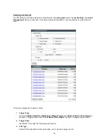
Page 31: ...rds in the SD card There are 3 categories of search criteria 1 Trigger Type It includes Motion Detection Digital Input Manual Trigger and Network Fail and Periodically as the type of triggered by events and Schedule Recording as the type of triggered by schedule 2 Trigger Time Input Date Time rage that recording was created 3 File Type Select the file type that is either video clips avi or picture...

Page 32: ...rk Fail and Digital Input Samba This page allows user to configure the file storage via Samba To begin with it click Enable Samba and then input the related information NOTE Samba can only support mounting a shared folder located in the root directory For example to mount a folder called Shared can be input the path as below IP Shared ...

Page 33: ...Event Handling There are 6 subdirectories in the Event category The 6 configuration groups are correlated A completed event setting may need to configure each part in sequence Event Server Media Motion Configuration Audio Detection Tamper Detection DI DO Setting Event List Event Server Media The Event Server is the configuration of where to send e g FTP server while Media is the sending file type ...

Page 34: ...media file to a FTP server when an event is triggered FTP Server address Enter the FTP server s address User Name Enter the user name of the FTP login account Password Enter the user name of the FTP login password Server Port Number Enter the server port of the FTP server The default is 21 Upload Path Enter the file path that files will be sent to Media Type There are 2 types of media file availab...

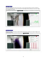
Page 35: ...just the detection Sensitivity and Object Size of the rectangle covered area NOTE By name implying the Sensitivity setting means the sensitivity level to the motion detection the higher value given makes the motion window more sensitive to the moving object Object Size indicates the trigger threshold A lower Object Size value means it is easier to exceed the value and thus trigger the motion event...

Page 36: ...ction to detect the monitoring area whether has any abnormal sound over the threshold this could be an event source to trigger event notification and alarms Tamper Detection With tamper detection the camera is capable to detect tampering and could be event source to trigger event notification and alarms ...

Page 37: ...om the initial the trigger is activated Digital output DO on the other hand can be one of the responding actions When its current status is different from the initial status the output is triggered The DI could also be configured as camera Day Night mode switch input to synchronize with Day Night signal output from an external illuminator or an external light sensor And DO could also output camera...

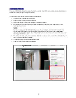
Page 38: ...igured events That is the selection of trigger condition s and the corresponding actions as well as the scheduling Up to 10 event objects can be configured To begin with it click on Add New button to extend for the detailed configurations ...

Page 39: ...cally Enable the system to perform the set Action periodically Tamper Detection Enable the event to detect the tampering event Audio Detection Enable the event to detect the audio event Action The selection of responding actions Digital output Check the box to enable the digital output as a responding action For detailed configurations go to DI DO Setting Upload files to a server This sort of acti...

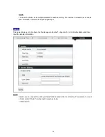
Page 40: ...ent anytime simply by pressing the button on the web page It will then start generating a video clip to SD card and sending email with the captured pictures The configurations are illustrated as below Step 1 Add Event Server Go to Event Event Server Media Event Server List Click on Add New button Choose Email and fill in the email server and recipients information ...

Page 41: ...ck the box to enable this event It can be deselected later with all the following settings remained b Give a name of this event setting e g MTrigger stands for Manual Trigger This is an identity of an object of event handling c Choose Select All for 24 7 as this event is required for that it can be triggered anytime d Select Manual Trigger for this event s trigger source This will activate the man...

Page 42: ...clip configured in Scenario 1 Step 1 Define the motion area Go to Motion Configuration page and define the MD area Step 2 Configure DI DO setting Go to DI DO Setting page to set up the Initial Status of the digital output NOTE The Initial Status is the normal state no event triggered of the DO pins In the case suppose that the connected illuminator can be driven by DC12V The initial status should ...

Page 43: ...nt handling c Select time frame in the schedule table for the requirement that is available from 00 00 to 08 00 every day d Select Motion Detection for this event s trigger source Suppose that all the 3 motion areas are enabled e Check the box to enable and select the SD card as the storage destination Choose Video for the configured media f Check the box to enable the digital output as the event ...

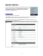
Page 44: ...ach subcategory will be described as below System Information The page gives details of the IP camera system In System Status the Model ID Firmware Version and MAC Address are listed The Camera Name and Location fields are revisable to identify a unit among multiple cameras installed The IP address info of this IP camera is listed in Network Status The RTSP Status field shows the video stream s be...

Page 45: ...lity of Internet access The IP camera system can therefore get updated with the time server NOTE To apply synchronize with NTP Server a Time Zone must be selected for referencing to the local time Synchronize with PC The PC connected to the IP camera can also be a date time synchronizer However if the PC is connecting from a time zone different from where camera is installed the system will pop up...

Page 46: ...lick on Enable Authentication check box and then apply To edit password for the default account click Edit to enter the configuration window To create a new account click Create User button Enter Account Password for this account with the group type on the Create account window The user account with Administrator authentication can do all the configurations Operator has the same rights as Administ...

Page 47: ...ommended to switch the IP setting to DHCP mode before exporting the backup file Otherwise all IP cameras will have the same IP address Firmware Upgrade There may be new released firmware for features update or issues fixed To upgrade the firmware for the system retrieve the firmware image file import to the system and then do the upgrade process LOG service The system operations and or process wil...

Page 48: ...47 Connectors LED Front and Back Panels I O connectors Pin definitions Schematic diagram of Digital I O Pin Signals Function 1 RX IN Digital Input 2 GND Ground 3 DO OUT Digital Out Focus Assist Button ...

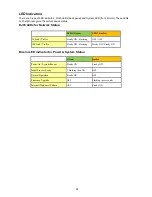
Page 49: ...Status Bicolor LED indicator for Power System Status Green Amber Power On System Reboot Steady ON Steady ON Initial Process Ready 3 Flashing then ON OFF Normal Operation Steady ON OFF Firmware Upgrade OFF Flashing per second Internal Hardware Failure OFF Steady ON LED1 Green LED2 Amber 10 Link Traffic Steady ON Flashing OFF OFF 100 Link Traffic Steady ON Flashing Steady ON Steady ON ...

Page 50: ...s until LED indicator flashes from Green light to Amber light Step 2 Adjust Focus Keep the camera pointing to the same scene during the tuning process Start tuning the focus in order to turn the LED Green If LED displays Red light it indicates the opposite turning direction Step 3 Get the Best Focus Value When camera gets correct focus the LED will become Green flashing Remain the camera s pointin...

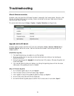
Page 51: ...re Upgrade 1 The latest firmware image is available on our official website 2 Make sure all other client connections are disconnected and current jobs such as recording are required to terminate 3 During the upgrading period DO NOT disconnect the power of the camera Otherwise the system unit might be damaged 4 The front LED indicator will be slow flashing in red during the upgrading process When i...

Page 52: ...51 Figure 1 Figure 2 Figure 3 ...

Page 53: ...Reset Button within 1 second the system will be restarted the LED Indicator will be steady amber during rebooting process Upon successful reboot the LED will be steady green during normal operation 2 Reset to factory default settings Press and hold the Reset Button over 5 seconds The LED will change from steady green to flashing green As LED flashing green then release reset button ONLY account pa...

Page 54: ...dio In Out Built in microphone External microphone and speaker Image Enhancement Image Settings AWB AES AGC IRIS Mode Off Auto Flickerless Mode On Off Exposure Gain Mode Auto Manual White Balance Auto Fixed Sharpness Saturation Brightness Contrast 17 level sensitivity Exposure 15level sensitivity Digital WDR Yes 8 level sensitivity DNR Auto On Off Privacy Zone Yes customized threshold privacy zone...

Page 55: ...l Block 1 in 1 out Network RJ 45 with LEDs Network indicator Audio In Out 3 5mm Phone Jack 1 in 1 out for external microphone speaker Built in Microphone Analog Video BNC X1 1 0Vp p 75Ω Reset Within 1 sec for rebooting system more than 10 sec until red LED starts to flash for loading default Bicolor LED Focus Power System Status Focus Assist Button YES Power Power Requirement DC 12V AC 24V 10 PoE ...

Reviews: