background image

V6

21

2-

58

1-

00

 0

9/0

9

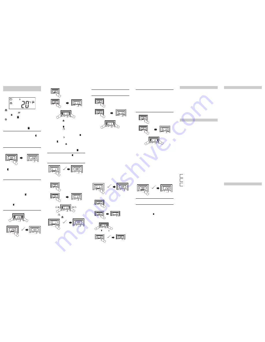
Standard display

Here you see an example of the standard display:

 „Comfort“ operating mode

• Actual temperature 
• Heating 

 is active in order to reach the comfort set-

point temperature   .

 is constantly displayed: The time has been syn-

chronised with the time switch (e.g. year time switch 

REG-K). Clock symbol flashes: The time has not (yet) 

been synchronised.

• Weekday  display 

3

 = Wednesday 

|

Note that the display of the weekday depends on 

the pre-settings. The electrician has set   , 
a specific weekday to 1. In some countries the 

first day of the week is not Monday, but Sunday, 

for example. The other numbers have different 

meanings accordingly (e.g., 2 = Monday, 

3 = Tuesday etc.).

Setting the setpoint temperature

The electrician has specified three setpoint tempera-

tures   ( for both heating and cooling):
• for comfort mode
• for standby mode
• for night operation

|

You see the setpoint temperature of the current 

operating mode. You can only change this set-

point temperature. In order to change the setpoint 

temperature of another operating mode, you first 

have to switch the operating mode (see „Setting 

the operating mode“).

|

The electrician specified   , within which limits 

this value can be changed (for example, within a 

minimum of 16 °C up to a maximum of 26 °C). You 

cannot set any value below or above these limit 

values. If the electrician made the appropriate 

setting   , the 4-gang push-button emits a warn-

ing sound as soon as you attempt to exceed 

these limit values.

Setting the room temperature control 

unit/display view

1x 5 s

+ 0,5°

- 0,5°

1x 5 s

1

2

=

Setting the operating mode

• b 0 = comfort mode 

Select this operating mode if you are staying in the 

room. The heating is set to the comfort setpoint tem-

perature (e.g. 21 °C  ).

• b 1 = standby mode 

Select this operating mode when you are not in the 

room over a longer period of time. The heating is set to 

the standby setpoint temperature (e.g. 18 °C  ).

• b 2 = night operation 

The heating is set to the night setpoint temperature 

(e.g. 15 °C  ).

• b 3 = comfort extension   (flashes)

Select this operating mode if you want to suppress 

night operation temporarily. The heating is set to the 

comfort setpoint temperature (e.g. 21 °C  ).

|

The electrician may have set   , the times at 

which the operating mode switches automatically 

from night operation to comfort mode and vice 

versa.

Setting the working day/holiday

• h 0 = holiday 
• h  1  =  working  day 

1

1x 5 s

2

1x 1 s

+

-

1x 5 s

=

1

1x 5 s

2

2x 1 s

1x 5 s

=

Setting the display mode

|

With the display mode, you can select which val-

ues you want to see in the display.

• d 0 = actual temperature (without decimal point)
• d 1 = setpoint temperature (to 0.5 degree accuracy)
• d 2 = temperature from external temperature sensor
• d  3  =  date
• d  4  =  time
• d 5 = fan speed
• d 6 = date and time in alternation
• d 7 = date, time and fan speed in alternation
• d 8 = actual and setpoint temperature in alternation
• d 9 = actual/setpoint temperature and time in alterna-

tion

• d 10 = actual/setpoint temperature and fan speed in al-

ternation

• d 11 = temperature from external temperature sensor 

and actual temperature

• d 12 = temperature from external temperature sensor, 

actual temperature and time in alternation

• d 13 = actual/setpoint temperature, date and time in al-

ternation

• d 14 = actual/setpoint temperature, fan speed and 

time in alternation

• d 15 = emperature from external temperature sensor, 

actual temperature, fan speed and time in alternation

Setting the background lighting

1

1x 5 s

2

3x 1 s

+

-

1x 5 s

=

1

1x 5 s

2

4x 1 s

4

+

1 =

10 =

...

=

1x 5 s

-

3

Setting the internal clock time and switching times

|

If the time is updated by an external time switch, 

the updated time is displayed here. If you change 

this time manually, it will be overwritten again by 

the time switch during the next update.

|

You can only use the control menu to adjust the 

switching times which have been pre-pro-

grammed via the ETS. Switching times which are 

not defined in the ETS are shown when they are 

called up in the display with „

--:--

“ and cannot be 

set using the push-buttons on the display.

t 0

 = time (either transmitted from the external time 

switch or from the internal clock)

t 1.1 

bis 

t 1.4

 = time channel 1, switching time 1-4

t 2.1 

bis 

t 2.4

 = time channel 2, switching time 1-4

3

Press central push-button and 

hold

 : he hour dis-

play for the selected time/switching time starts to 

flash.

4

Press the left or right push-button on the display: 

Set the hours as desired

5

Press the central push-button 

briefly

 : The minute 

digits now flash.

6

Press the left or right push-button on the display: 

Set the minutes as desired.

7

Press the central push-button 

briefly

: The set time 

(t...) appears again.

8

Press the central push-button 

briefly

 again: Save 

the desired new setting.

|

Synchronise the time via an external time switch 

to guarantee precision over a long period of time.

Selecting the setpoint temperature or operating 

mode directly

The electrician specified   , whether you can access 

and adjust the setpoint temperature or the operating 

mode directly using the right/left push-button, or whether 

none of these functions is activated.

1

1 x

 push-button 

left/right

 – 

short

 push-button ac-

tion.

The menu command „Set setpoint temperature“ or „Set 

operating mode“ is displayed with the last set value. 

Change the value by pressing the left or right push-but-

ton on the display. The value is saved directly; you don‘t 

have to save it separately. After approx. 5 s, the room 

temperature control unit returns automatically to the 

standard display.

1

1x 5 s

2

5x 1 s

+

-

1x 5 s

=

Push-button assignment

Time control channel 1

Time control channel 2

Alarm functions

Setpoint adjustment valid until:


Operation mode change / Permanent

Week starts (1):

 on Fri / Sat / Sun / Mon

Direct selection:

 Setpoint temperature / Operation 

mode / None

Other display views

APL.

Application not loaded or faulty

E 2

Heating setpoint temperature = cooling setpoint 

temperature

E 3

ETS application is not compatible

E 4

Upper control value range = lower control value 

range

E 5

FRAM error

E 6

Error in temperature sensor

E 7

STACK error

E 8

RAM error

E 9

Buffer error

Presettings table

Push-button 1 _____________________________
Push-button 2 _____________________________
Push-button 3 _____________________________
Push-button 4 _____________________________
Push-button 5 _____________________________
Push-button 6 _____________________________
Push-button 7 _____________________________
Push-button 8 _____________________________

Switching 

time


1


2


3

4

Time

___:___ ___:___ ___:___ ___:___ 

Function:

_______________________________

Switching 

time


1


2


3

4

Time

___:___ ___:___ ___:___ ___:___ 

Function:

_______________________________

Alarm sounds if actual temperature is less than 

the frost protection temperature 

or

Alarm sounds if the setpoint adjustment limit is 

exceeded
Others:

____________________________________

Heating setpoints in °C/°F Adjustment limit in °C/°F
Comfort:

______

min: _____ max: _____

Standby:

______

min: _____ max: _____

Night:

______

min: _____ max: _____

Heating setpoints in °C/°F Adjustment limit in °C/°F
Comfort:

______

min: _____ max: _____

Standby:

______

min: _____ max: _____

Night:

______

min: _____ max: _____

Frost 

protection:

______

min: _____ max: _____

Heat 

protection:

______

min: _____ max: _____

If you have technical questions, please contact the Cus-

tomer Care Center in your country. 
www.schneider-electric.com
This product must be installed, connected and used in 

compliance with prevailing standards and/or installation 

regulations. As standards, specifications and designs 

develop from time to time, always ask for confirmation of 

the information given in this publication.

Technical data

Power supply:

via KNX

Connection:

Bus connecting terminal

Display elements

Push-button 

2-/4-gang:

1x Display
1x operational LED

Push-button 2-gang: 4x Status LED
Push-button 4-gang: 8x Status LED

Piezo buzzer

Operating elements

Push-button 

2-/4-gang:

3 push-buttons to navigate 

menu

Push-button 2-gang: 4 push-buttons
Push-button 4-gang: 8 push-buttons

IR receiver 

(angle of reception: 60°)

Measuring range:

0 to 40 °C

Measuring accuracy:

± 1 K, depending on installa-

tion site; Offset can be config-

ured

Controller type:

2-step
Continuous PI controller
Switching PI controller (PWI)

Controller mode:

Heating with 1 controller 

output
Cooling with 1 controller out-

put
Heating with 2 controller out-

puts
Cooling with 2 controller out-

puts
Heating and cooling with 

separate controller outputs
2-step heating with 2 controller 

outputs
2-step cooling with 2 controller 

outputs
2-step heating and 2-step 

cooling with 4 control outputs

Type of protection:

IP 20

Schneider Electric Industries SAS

Summary of Contents for MEG6212-03 Series

Page 1: ...operating instructions of your printer to find out which type of foil strips you can print Only use the coloured foil strips enclosed as the base since this ensures that the push button LEDs under the...

Page 2: ...button and hold he hour dis play for the selected time switching time starts to flash 4 Press the left or right push button on the display Set the hours as desired 5 Press the central push button brie...

Page 3: ...th RTCU and FanCoil 1817 1 0 Media type Twisted Pair Product name Push button 4 gang plus room temp control IR Order number MEG6214 40xx MEG6214 41xx Manufacturer Merten Product family 2 3 Push Button...

Page 4: ...and factor parameters The actual time is giv en by the multiplication of the two values Exam ple Base 1 second factor 3 gives 3 seconds The bold values in a table are the values set dur ing factory co...

Page 5: ...can be changed using the menu buttons on the push button see operating instruc tions If you use room temperature control Control general tab additional possible settings appear You can specify whether...

Page 6: ...d via the feedback object Display Parameter Settings User menu enabled Yes No Adjust operation mode during frost heat protection Yes No Set display mode multiple names appear during the change Actual...

Page 7: ...ton Two objects 1 bit 1 byte can also be transmitted in any combination when the push button is pressed Status indication The status LED can Be switched on or off continuously Light up when pressed fo...

Page 8: ...B not equal to 0 Flashes when switch value object A equals 0 Flashes when switch value object B equals 0 Flashes when status feedback object equals 1 Flashes when status feedback object equals 0 Opera...

Page 9: ...iod can be parameterised When switching takes place an ON OFF telegram is sent via the switch object When dimming dimming up or dimming down is carried out via the 4 bit dimming object the parameters...

Page 10: ...rised You can specify whether a stop telegram is to be trans mitted when the push button is released If you have enabled the transmission of a stop telegram a stop tel egram will be transmitted via th...

Page 11: ...the next time the push button is activated for a long period the exact period can be pa rameterised When a stop step telegram has been transmitted to ad just the slats a stop step telegram for the sam...

Page 12: ...long operation of the push button Status indication The status LED can Be switched on or off continuously Light up when pressed for a long period and go out when released Flash Display the status of o...

Page 13: ...are 1 bit 2 bit priority con trol 4 bit 1 byte in steps or infinitely Push button X Parameter Setting Edge function Normal operate release Number of objects One Two Push button X edges object A B Para...

Page 14: ...ject values you may need to set the Read flags manually The following activation sequence chart shows the phases into which the pulse edge function is divided Example 1 Object A 1 bit Sends 1 None Non...

Page 15: ...ends cyclically Toggles and is not sent Toggles cyclically sends immediately then cyclically Toggles cyclically only sends cyclical ly Toggles cyclically and is not sent Sends its value Sends its valu...

Page 16: ...the toggled value is transmitted and a new cycle time is started Subsequently it is always toggled cyclically and the new value is transmitted Toggles cyclically only sends cyclically If no cycle time...

Page 17: ...sed cy cle time e g 3 minutes it switches it back off again With a long press of the push button the same function is carried out but with a longer cycle time e g 6 min utes Number of objects 2 object...

Page 18: ...of the switch ac tuator Number of objects 1 object A Object A 1 bit Object A Action on release before the long operating time has elapsed Sends 1 immediately and then cyclically Action on achieving t...

Page 19: ...transmits the value which it currently has Therefore you can for example transmit a value with the sending group address which was previously re ceived via another group address No action Available va...

Page 20: ...and value B is transmitted after one cycle time regardless of wheth er a cycle time is already running or not staircase lighting timer function None stops cyclical sending No action is carried out and...

Page 21: ...step value Reduce current object value once Reduce the current object value once by the parame terised step value Any active cycle time is terminated Reverse slide direction and send cyclically If no...

Page 22: ...gain after the last possible step Example Value 1 0 value 2 255 step size 100 the following values are sent 39 78 0 39 78 0 etc Decrease stepwise within limits The value is reduced by one step value a...

Page 23: ...t different actions for short and long presses of a push button both for when the push button is pressed and for when it is released You can also set a cycle time which can be parameterised for each o...

Page 24: ...ong operating time has elapsed Sends value 2 Action on achieving the long operating time Toggles Action on release after achiev ing the long operating time Toggles cyclically sends immedi ately then c...

Page 25: ...on mode Parameter Settings Number of operation modes between which you want to toggle One Two Three Four Operation mode 1 Comfort extension operation Comfort operation Standby operation Night operatio...

Page 26: ...push button s internal scene module and must be identical to the scene addresses in the module The scene addresses entered with this function are not transmitted to the bus Communication objects You...

Page 27: ...Actuator group 7 is a special group which allows you to transmit values with 16 bits Specifying scene addresses and values For each scene you specify the scene address via which the scene on the exte...

Page 28: ...2 Time control tab Set the Request time synchro nisation via the bus parameter to Yes 3 Time control tab For the Behaviour when syn chronisation fails parameter select whether the switching commands a...

Page 29: ...Switching time 3 18 00 Switching time 4 22 00 The switching times are not carried out until the time has been set once via the control menu or via the time object When a change is made from a holiday...

Page 30: ...re sensor integrated into the push button However you can also measure the temperature via an external sensor and transfer it to the controller via the bus which then takes it fully or partially into...

Page 31: ...peration mode only or All operation modes Setpoint adjustment affects current operation mode only In this setting the setpoint temperature of the current operation mode is changed You can select wheth...

Page 32: ...econfigured is active The corresponding setpoints then also apply If the setpoint that was set is changed via the control menu and the value is higher or lower than the set limit an acoustic signal ca...

Page 33: ...button operation mode push button function comfort extension operation or The bus object Comfort extension The parameterised time for the comfort extension runs to an end and can then be restarted by...

Page 34: ...ht operation mode This operation mode enables you to reduce or increase the room tem perature to a greater extent during the night or over the weekend In this operation mode you use a 1 tele gram to s...

Page 35: ...mode has the highest priority A 0 telegram terminates the dewpoint alarm and the new operation mode is set The operation mode is the result of current informa tion from the objects Comfort input and N...

Page 36: ...ing frost heat protec tion No Frost heat protection object or Temperature jump detection Disable object Dewpoint alarm object Dewpoint alarm 1 Cooling Yes 0 No Correcting variable cooling 0 1 0 1 Fros...

Page 37: ...uator Electric convector Night storage heating Ceiling heating Cooling In the cooling control mode the current actual temper ature is compared with the current setpoint tempera ture If the actual temp...

Page 38: ...ed to con tinue to heat the room above the setpoint temperature If you have configured the heating and cooling setpoint temperatures to be the same the insensitive zone is set to 0 K The air condition...

Page 39: ...n not adjust the values for standby or night operation Two stage heating or cooling In order to shorten the heat up phase with slow heating systems e g underfloor heating a second more re sponsive hea...

Page 40: ...its ad vantage is that the room temperature is not constant but changes continuously reducing comfort particularly when heating and cooling systems are slow to react To counteract this effect you can...

Page 41: ...he controller Warm water heating Underfloor heating Electric heating Fan convector Split unit Cooling ceiling You can also set the control parameters for the propor tional range and the reset time man...

Page 42: ...ceiling with motorised valve drives Switching electric radiator heating Air conditioning with 4 duct 2 circuit air convector sys tem e g switching valve drives Temperature limitation using shading fa...

Page 43: ...t status object here If you want to display the system s status using visuali sation software there is one 1 byte status object and one 2 byte status object available for this purpose Structure of the...

Page 44: ...e The following formula applies Actual temperature measured temperature correc tion value If you also use an external temperature sensor you can set the percentage proportion at which the external ac...

Page 45: ...system types for which the recommended parameters have already been preconfigured Howev er if you have sufficient specialised knowledge you can also set the control parameters as required For 2 step...

Page 46: ...water when the heating is switched off for a longer period of time e g over the summer When the valve protection is switched on the valves are opened for a preset dura tion 100 on the controller outpu...

Page 47: ...variables Parameter Setting Function Object name Type Prio Flags Behaviour Control Current actual tem perature output 2 byte Low CRT Transmit read out Control Current actual tem perature input 2 byte...

Page 48: ...ow CRT Transmit read out Control Correcting variable heating basic level 1 byte Low CRT Transmit read out Control Correcting variable heating additional level 1 bit Low CRT Transmit read out Control C...

Page 49: ...iour when bus voltage fails The operation LEDs status LEDs are switched off to gether with the display including the background light ing Merten GmbH Solutions for intelligent buildings Serv ice Cente...

Reviews: