background image

Page 8

3.7 Configuration of Zero and Span Procedures

The ZERO and SPAN Buttons are under the transmitter’s
nameplate. The ZERO, SPAN, ZERO TRIM, ZERO ADJ, Units,
Range, Dampening, LCD and decimal set functions are configurable
using the ZERO / SPAN buttons. 

Zero/Span Configuration Process

Remove both name plate screws on the upper part of transmitter. 
Remove top name plate to access the Zero and Span Buttons. 
(following Figure 3-4)
1. Zero Configurations

Set the current process value for Lower Range Value (4 mA).
Apply zero pressure for 10 seconds and push the Zero Button 
for 5 seconds. The LCD should display “Zero”. Push the Zero 
button for 3 seconds, after 1 second the LCD should display 
“-ZE-”. This message means the zero configuration is 
finished. If the zero configuration failed, the LCD will display 
“SPEr” or “SEtE”, try repeating the zero configuration steps.

2. Span Configurations

Apply the desired pressure for 10 seconds and push the Span 
Button for 5 seconds. The LCD should display “Span”. Push 
the Span button for 3 seconds, after 1 second the LCD should 
display “-SP-”. This message means that the span 
configuration is finished. If the span configuration failed the 
LCD will display “SPEr” or “SEtE”, try repeating the span 
configuration steps.

• Please refer to Appendix 1 for the button error and LCD display 

message.
The other functions supported by the ZERO / SPAN Buttons are 
below. 

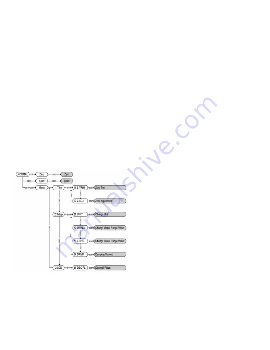
[Menu Tree for Zero+Span Button Function]
1. Moving between menus: Zero
2. Enter or moving to sub menu: Span
3. Moving to top menu: Zero+Span

Press the button for 3 seconds to execute each function. After
3 seconds press the Zero+Span buttons, the LCD display 
will change from Menu to Trim. To see the next menu, press 
the Zero button for 3 seconds. Use the Zero button to move 
down the directory. 

Use the Span button to select the displayed menu. The same
procedure will be used for the sub menus.

Caution: 30 seconds without any action, the button function will
return to normal operation. 

4. How to select a numerical value

A Functions use numerical values: 12 Zero Adjustment, 22 

Change Upper Range Value, 23 Change Lower Range Value, 
24 Dampening Second

B How to select numerical value: First, select an increasing rate

(10

n

), then change each decimal value to increase or 

decrease as wanted. For example, select 3810 : Select 
increasing rate 1000 -> Increase 3 times -> Select 
increasing rate 100 -> Increase 8 times -> Select 
increasing rate as 10 -> Increase 1 time

C To select the increase / decrease steps: SelInc message will 
be displayed on the bottom of the LCD. Select parameter and  

press the Zero button : The decimal value will be changed 
when the Zero button is pressed. After set, press the span 
button to execute the parameter.

D To set the required values using Zero/Span buttons: VALUE 

message will be displayed on the bottom of the LCD. 

1. Press the Zero button, the menu will increase 1 item.
2. Press the Span button, the menu will decrease 1 item.
3. After setting, save the parameter by pressing the 

Zero+Span buttons.

E To set the final value, repeat C and D.
F

After setting the final parameter, exit the menu by pressing the 
Zero+Span buttons. 

5. Exercises for each function

ZERO TRIM

1. Access the menu by pressing the Zero+Span buttons.
2. Move to the sub directory using the Span button until the 

1 TRIM message appears on the display.

3. Change the Zero Trim Function by using the Span button

until the 11 Z-TRIM message appears on the display.

ZERO ADJUSTMENT : Change the PV value to 14

1. Exit the menu by pressing the Zero+Span button. 
2. Moving thru the sub directory using the Span button 

until 1 TRIM message appears. 

3. Moving thru the sub directory using the Zero button 

until 11 Z-TRIM message appears.

4. Access the Zero Adjustment function by pressing the  

Span button until the 12 Z-ADJ messages appears.

5. When the SelInc message appears, press the Zero button 

repetitively until the 10.0 message appears on the LCD. 
Set the value by pressing the Span button.

6. When VALUE message appears, change the LCD value 

to 10.0 and press the Zero button, then press the 
Zero+Span buttons.

7. When Sellnc message appears, change the LCD value to 

1.0 and press the Zero button, then set the value and 

press the Span button. Press the Zero+Span buttons after 

the LCD value changes to 14.0.

8. To save the settings, press the Zero+Span buttons until 

the SelInc message appears. 

CHANGE UNITS

1. Access the menu by pressing the Zero+Span buttons.
2. Moving to next menu by pressing the Zero button until the 

1 TRIM message appears. 

3. Moving thru the sub directory press the Span button until 

the 2 SETUP message appears.

4. Press the Span button to access 21 UNIT, press Span 

again to access Change Unit.

5. Save the values by pressing the Span button when the 

desired value is displayed on the LCD. 

P-3100:TEMPLATE  3/1/10  11:27 AM  Page 9

Summary of Contents for 3100

Page 1: ...one 219 879 8000 www dwyer inst com P O BOX 373 MICHIGAN CITY INDIANA 46361 U S A Fax 219 872 9057 e mail info dwyer inst com Specifications Installation and Operating Instructions Series 3100 Explosion Proof Differential Pressure Transmitter ...

Page 2: ... of Alarm and Security Jumper Procedures 3 7 Configuration of Zero and Span Procedure 3 8 Commissioning on the Bench with HHT Chapter 4 Installation 4 1 Overview 4 2 Safety Messages 4 3 Warning 4 4 Commissioning on the Bench with Hand Held Terminal 4 5 General Considerations 4 6 Electrical Considerations 4 7 Wiring 4 8 Mechanical Considerations 4 9 Environmental Considerations Chapter 5 On line Op...

Page 3: ...oint 1 1 Using This Manual The operating manual provides information on installing operating and maintaining the Mercoid Model 3100 Smart Pressure Transmitter The Chapters are organized as follows Chapter 2 Handling Cautions Chapter 2 provides instructions on commissioning and operating the Model 3100 Smart Pressure Transmitters Informations on software functions configuration parameters and on li...

Page 4: ...PC Configurator The transmitter s various variables in host are able to be changed configured and calibrated by users The HART Communication between DC power supply and transmitter requires a 250 550 Ohm resistance 1 3 Software Compatibility The Mercoid Smart Pressure Transmitter s software is implemented at the factory The following functions can be configured using a HHT Hart Communicator Suppor...

Page 5: ...d vibration are minimal Where the area classification does not exceed the explosion proof rating Where maintenance is easy Where the transmitter can be handled easily Be cautious of process connections leaking 24 VDC Power Supply is 11 9 Vdc 45 Vdc For HART communication resistance on transmitter terminal loop should be between 250 550 Ohms When mounting the transmitter an appropriate bracket shou...

Page 6: ...Sensor Zero Trim apply a pressure for zero in advance Sensor Zero Trim the sensor when the pressure is sufficiently stabilized after approximately 10 seconds 3 There are two ways to pressure zero One way is to apply zero differential pressure making pressure the same on both the high and low side The other is to close High and Low side of a 3 valve manifold and open the equalizing valve 4 Sensor Z...

Page 7: ...stomer use metal conduit wiring or twisted pair shield cable for signal wiring to conform with EMC regulation when installing the Mercoid 3100 transmitters Chapter 3 Transmitter Functions 3 1 Overview This Chapter contains information on operating the Model 3100 Tasks that should be performed on the bench prior to installation are explained in this chapter 3 2 Safety Message Procedures and instruc...

Page 8: ...ers are protected 2 Physically removing Zero and Span Magnetic Buttons you are unable to regulate zero and span locally 3 5 1 Security Jumper EEPROM Write Protect Prevents the transmitter s configured parameters from being changed 3 5 2 Zero and Span Buttons By removing the Magnetic Buttons you can t configure the transmitter using the Zero and Span locally 3 6 Configuration of Alarm and Security ...

Page 9: ...select 3810 Select increasing rate 1000 Increase 3 times Select increasing rate 100 Increase 8 times Select increasing rate as 10 Increase 1 time C To select the increase decrease steps SelInc message will be displayed on the bottom of the LCD Select parameter and press the Zero button The decimal value will be changed when the Zero button is pressed After set press the span button to execute the ...

Page 10: ... button until the Decimal Place message appears the decimal place will appear on the second line of the LCD as follows 7 The first line on the LCD will display 0 0 8 The Decimal Place can be changed by pressing the Zero button Save the setting by pressing the Span button after the decimal place has been selected 9 The set value will display the PV value and Engineering value 10 The LCD will displa...

Page 11: ...an be commissioned before and after installation Commissioning is easier if the transmitter is configured on a bench with an HHT before installation 4 5 General Considerations The transmitter can be mounted near the process to minimize piping Keep in mind that easy access is required for personnel field calibration and installation Install the transmitter in an area with minimal vibration shock an...

Page 12: ...t the process wires to the transmitter 4 7 3 Connecting External Wires to Transmitter Terminal Box 1 Open the cover indicated FIELD TERMINAL Do not open the cover if the transmitter is located in an explosion proof area and powered Connect the power supply to the terminal indicated PWR left terminal and in the central terminal Do not connect power supply to terminal TEST It will damage the test di...

Page 13: ...e below 10 ohms Note In case of Built in Lightening Protector Grounding should satisfy Special KS requirements grounding resistance 10 ohm or less b There are ground terminals on the inside and outside of the transmitter Either of these terminals may be used c Use 600V insulated PVC wire for grounding 4 7 6 Power Supply Voltage and Load Resistance When configuring the loop make sure that the exter...

Page 14: ...n in Hazardous Location The transmitter is designed with an explosion proof housing Installation environment must not exceed the explosion proof rating Chapter 5 On Line Operation 5 1 Overview This chapter describes how to configure the 3100 Smart Pressure Transmitter The transmitter can be configured in On Line or Off Line mode In On Line Mode a compatible HHT or PC configuration device must be u...

Page 15: ...bic feet hectoliters 5 5 3 4 20mA Configuration Set the Zero and Span for the 4 20mA analog output 5 6 Detailed Setup 5 6 1 Set Fail Mode When the sensor or microprocessor is not operating properly the transmitter will output 3 75mA or 21 75mA based on the Fail Mode setting 5 6 2 Set Dampening Time The Dampening Seconds value changes the response time of the transmitter to smooth out variations ca...

Page 16: ...im when first commissioning the transmitter on site There are three ways to trim the sensor Sensor zero trim full trim and zero adjustment Sensor zero trim is a one point adjustment typically used to compensate for the mounting position Two point trim is a full sensor trim in which two accurate pressures are applied equal to or greater than the range values and the output is linear You should alwa...

Page 17: ...for a 250 550 ohms resistance between the power supply and HHT Check for adequate voltage to the transmitter the transmitter requires 11 9 45 Vdc Check for intermittent shorts open circuits and multiple grounds Connect HHT and enter the transmitter test mode to isolate a sensor failure Check for dirty or defective terminals interconnecting pins or receptacles Check the output voltage of the power ...

Page 18: ...nics module and the other contains all wiring terminals and communication terminal 6 4 2 2 Fail Mode Jumper Switch and EEPROM Write Fail mode jumper switch and EEPROM Write is located behind the front cover Figure 6 2 Structure of Housing Figure 6 3 Structure of Electronics Module Page 17 Figure 6 1 Test Terminals ...

Page 19: ...lue is over limit 10 Zero Trim done Setting Limit error when executing Zero button function Setting Limit error when executing Span button function Zero button function done Span button function done Zero Adjustment done Configuration completed using buttons Limit error when executing other setting function Over Values for LCD Sensor Code Error Flash Setting Data Reset Flash Setting Data Reset Pro...

Page 20: ...010 Dwyer Instruments Inc Printed in U S A 3 10 FR RA 443807 00 DWYER INSTRUMENTS INC Phone 219 879 8000 www dwyer inst com P O BOX 373 MICHIGAN CITY INDIANA 46361 U S A Fax 219 872 9057 e mail info dwyer inst com ...

Reviews: