T-SI-86.70/131
n
May 2000
7
E. Installing the handset
1. Remove the center console storage box and
locate the coaxial cable/RJ-45 data cable
assembly under the box.
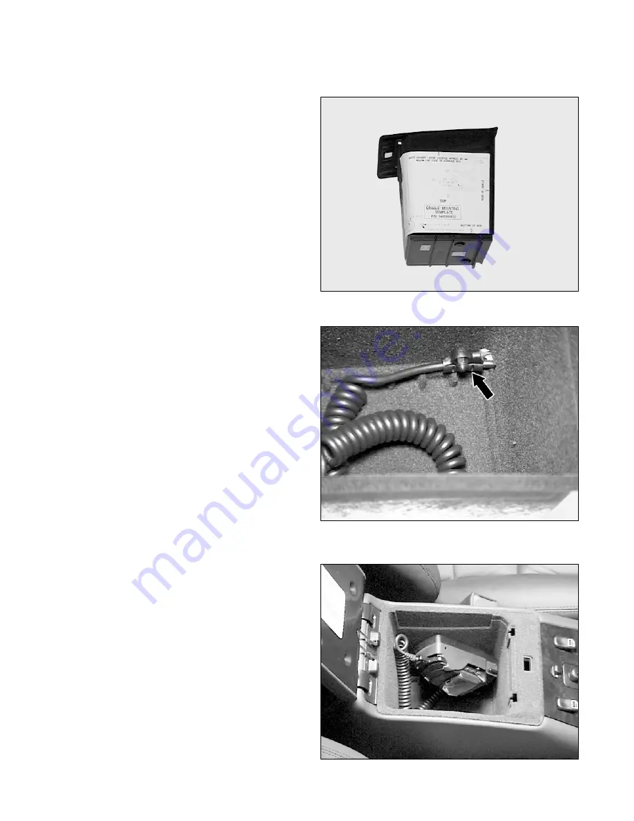
2. Place the template on the storage box
(Figure 12).
3. Drill one 19-mm (3/4-in.) hole and five 4.5-
mm (3/16-in.) holes in the storage box where
indicated on the template.
Figure 12
P82.70-2952-01
4. Route the coil-cord through the 19-mm
opening and secure the coil-cord strain relief
to the storage box using the 4.5-mm strain
relief hole and an M4 x 14 screw with M4
acorn nut (Figure 13).
Figure 13
P82.70-2953-01
5. Mount the cradle to the storage box with four
M4 x 8 screws (Figure 14).
Note:
The cradle release buttons should be
pointing toward the bottom of the box.
6. Connect the RJ-45 and mini-UHF connectors
from the coil-cord to the mating vehicle
connectors in the center console.
7. Reinstall the storage box.
8. Attach the handset battery, connect the coil-
cord, and place the telephone into the cradle
(Figure 14).
9. The connection point of the antenna lead
installed in step B5 will depend on the level of


