Installation and Basic Operation
Rev 1.4
Mellanox Technologies
30
13.
Check the Status LEDs and confirm that all of the LEDs show status lights consistent with
normal operation.
2.4.3 Grounding the Gateway
Make sure to connect the ground post to a valid electrical ground. Use a grounding lug and a
ground wire of sufficient capacity to safely convey a potential discharge. A ground wire of AWG 6
or 4mm diameter is recommended for grounding this device. The chassis is concurrently grounded
through each of the PSUs. Only connect the PSU cords to properly grounded outlets. Do not rely
on the PSU grounds. It is absolutely necessary to connect the grounding post. Make sure the con-
nections are solid and permanent. If you choose to not use the ground screw, make sure that the
rack is properly grounded and that there is a valid ground connection between the chassis of the
gateway and the rack. Test the ground using an Ohm meter.
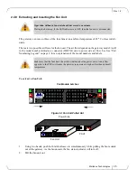
Figure 20: Ground Connection
Check to determine if your local or national electrical codes require an external ground to all IT
components.
2.4.4 Disassembling the Gateway from the Rack
To disassemble the gateway from the rack:
1.
Put on an ESD strap and connect to a valid ground.
2.
Shut down the gateway using the procedure in Section 2.4.6.
When the gateway is plugged in, the status LED may be RED for up to two minutes
until the system completes booting up.
Warning: Any yellow or red status LED is cause for concern and must be dealt with
immediately.
Some national and/or local codes may require IT components to be bonded and exter-
nally grounded (not including the power cord ground). You must follow all national
and local codes when installing this equipment.


