background image

Ensure that the instrument is properly earthed. The test set must be connected to a 
socket (receptacle) with a protective earth (ground) conductor. 

Before connecting the instrument to the mains power supply, ensure the voltage 
selector located on the mains input panel is set to the required voltage. The correct 
fuse value should be fitted for the supply voltage (See Specification). The fuse holders 
are located next to the supply inlet.

Power cord 

If the power cord plug is not suitable for your type of socket outlets, do not use an 
adaptor. You should use a suitable alternative power cord, or if necessary change the 
plug by cutting the cord and fitting a suitable plug. 


The colour code of the cord is:


Earth (Ground) 

Yellow / Green 


  Neutral 

 Blue

  Phase 

(Line) 

 Brown

If using a fused plug, a 3 Amp fuse to BS 1362 should be fitted.


Note: A plug severed from the power cord should be destroyed, as a plug with bare 
conductors is hazardous in a live socket outlet.

Oil Sampling

The relevant test specification will give advice on the best methods to use when 
sampling oil.  Contamination of the oil may lead to misleading results. Always run off 
a small amount of oil before sampling and ensure that the flow of oil is steady.

Preparing the Oil Test Vessel

Optional vessels are available for testing to national specifications (See table and 
Accessories). Some specifications require stirring of the oil sample as well as different 
test electrode shapes. Once the correct vessel has been chosen for the required test 
the electrode gap should be set. This is achieved by adjusting the threaded nut on 
the side of the vessel. Small adjustment of the gap can be made by hand tightening 
the nuts and rotating the spindle. A slot is provided on the end of the spindle for this  
purpose.

A set of individual 0,5 mm feeler gauges is provided for accurate measurement of the 
gap. Gauges can be combined to measure from 1 mm to 4 mm. (see page 12) 

Clean the vessel in accordance with the instructions given in the relevant test 
specification. Allowing space for the lid to be fitted, fill the vessel with the oil sample. 
The amount of oil required will depend upon the type of lid used. Load the vessel in 
the test chamber, connecting the motor power cable, if fitted, and carefully shut the 
door so that the safety interlock switch operates.

Preparing the Oil Test Set

5

Operation

Summary of Contents for OTS60SX/2

Page 1: ...M OTS60SX 2 Semi Automatic Oil Test Set User Guide...

Page 2: ...ampling 5 Preparing the Oil Test Vessel 5 Control Panel 6 Breakdown Testing 6 Withstand Testing 6 Warning messages 7 Testing to National Standards 7 Sampling and Testing Oil for Dielectric strength 8...

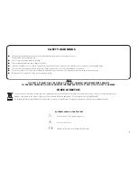
Page 3: ...sting Replacement fuses must be of the correct type and rating NOTE THE TEST SET MUST ONLY BE USED BY SUITABLY TRAINED AND COMPETENT PERSONS TO PREVENT DAMAGE DO NOT TRANSPORT INSTRUMENT WITH TEST CEL...

Page 4: ...sted according to breakdown specification by using a suitable sequence of tests The instrument is constructed in a strong sheet steel case Handles are provided for ease of transportation A pouch is lo...

Page 5: ...f the oil may lead to misleading results Always run off a small amount of oil before sampling and ensure that the flow of oil is steady Preparing the Oil Test Vessel Optional vessels are available for...

Page 6: ...left on the display until the next test is started If no breakdown occurs the high voltage will rise to 60 kV At this point the test voltage is cut off and this maximum value left on the display A tes...

Page 7: ...60SX 2 Oil Test Set The test vessel must be kept scrupulously clean Before each use dismantle the test vessel clean and dry re assemble and set the electrode gap to 2 54 mm 0 100 inch Dismantling the...

Page 8: ...l and the sampling apparatus as the condition of the oil itself After cleaning the apparatus it should under no circumstances be wiped dried or even handled with a dusty or fibrous cloth as loose dust...

Page 9: ...revent contamination is necessary when a test is to be made on a bulk delivery tanker and on all occasions when a high value of dielectric strength is anticipated The procedure suggested above should...

Page 10: ...3 min 3 min 5 min 5 min 3 min 3 min 3 min 3 min 3 min 3 min 3 min 3 min 10 min 3 min Rate of rise of voltage 2 kV s 3 kV s 0 5 kV s 0 5 kV s 2 kV s 2 kV s 2 kV s 2 kV s 2 kV s 2 kV s 2 kV s 3 kV s 3...

Page 11: ...n with automatic 1 minute timer for Withstand testing Display 0 0 60 0 kV LED digital display HV on LED Ramp rate LED Measurement Accuracy 2 3 digits Controls Start Pause Stop Ramp Rate select and Pow...

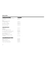
Page 12: ...Accessories Carrying Case 6420 106 Test Vessels 0 5 l for IEC156 spherical electrodes 6320 233 0 5 l for IEC156 with stirrer spherical electrodes 6320 236 0 5 l for VDE0370 mushroom electrodes 6320 2...

Page 13: ...contact Megger LImited or Megger Archcliffe Road Valley Forge Corporate Center Dover 2621 Van Buren Avenue Kent CT17 9EN Norristown PA 19403 England U S A Tel 44 0 1304 502243 Tel 1 610 676 8579 Fax...

Page 14: ...333 3201 T 33 1 30 16 08 90 F 1 214 331 7399 F 33 1 34 61 23 77 OTHER TECHNICAL SALES OFFICES Toronto CANADA Sydney AUSTRALIA Madrid SPAIN Mumbai INDIA and the Kingdom of BAHRAIN Megger products are...

Reviews: