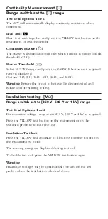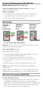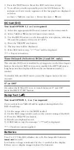
Continuity Measurement [
Ω
]
Range switch set to [
Ω
] range
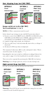
Test Lead options 1 or 2
The MFT will automatically display continuity resistance when
connected.
Lead Null
Short test leads together and press the YELLOW test button on the
instrument or Switched Probe.
Continuity Buzzer (
Z
)
The buzzer will sound automatically when a circuit is made (default
threshold <2
Ω
)
Buzzer Threshold (
Z
)
Select BUZZER range and press the ORANGE button until required
range is displayed.
Options, 2
Ω
, 5
Ω
, 10
Ω
, 20
Ω
, 50
Ω
, and 100
Ω
Warning:
Ensure the circuit to be tested is disconnected and
isolated before starting testing.
Insulation testing [M
Ω
]
Range switch set to [250 V, 500 V or 1 kV] range
Test Lead Options 1 or 2
For insulation voltage range select 250 V, 500 V or 1 kV as required.
Press the YELLOW test button on the instrument or on the
switched probe to activate the test.
Insulation Test lock
Press the YELLOW test and RED lock buttons together to lock on
the insulation test mode.
The warning triangle is displayed during test lock.
To disable test lock press the YELLOW test button again.
Warning:
Hazardous voltages may be continuously present on the test
probes when the test button is locked down.


