

FAULT LOCATING
AVTM651070 Rev B Nov 2006
33
Ground Return Probe Insertion
Circuitry between the ground spikes provides a path for current in the soil
returning to the GROUND ROD. The current enters one spike of the
GROUND RETURN PROBE and exits the other spike. The GRP should be
inserted into the soil with consistent force and depth.
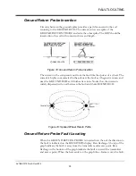
Figure 18: Ground Return Probe Insertion
The current in the soil spreads out from the fault like the spokes of a wheel. The
current is highly concentrated in the soil near the fault as it begins its return, and
near the GROUND ROD as it finishes its return. Notice that the current is
widely dispersed in the soil between the fault and the GROUND ROD.
Figure 19: Spoked Wheel Return Paths
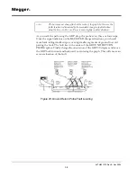
Ground Return Probe Fault Locating
When the GROUND RETURN PROBE is inserted into the soil the direction to
the fault is indicated on the RECEIVER’S display. Bars flashing at the top of the
graph indicate the fault is away from the transmitter and access point. Bars
flashing on the bottom of the graph indicate the fault is toward the transmitter
and access point. When the bars center on the graph the a -frame is over the fault.
Summary of Contents for L1070
Page 2: ...L1070 and L1071 Portable Locator Instruction Manual...
Page 4: ......
Page 8: ...AVTM651070 Rev B Nov 2006 iv M...


