background image

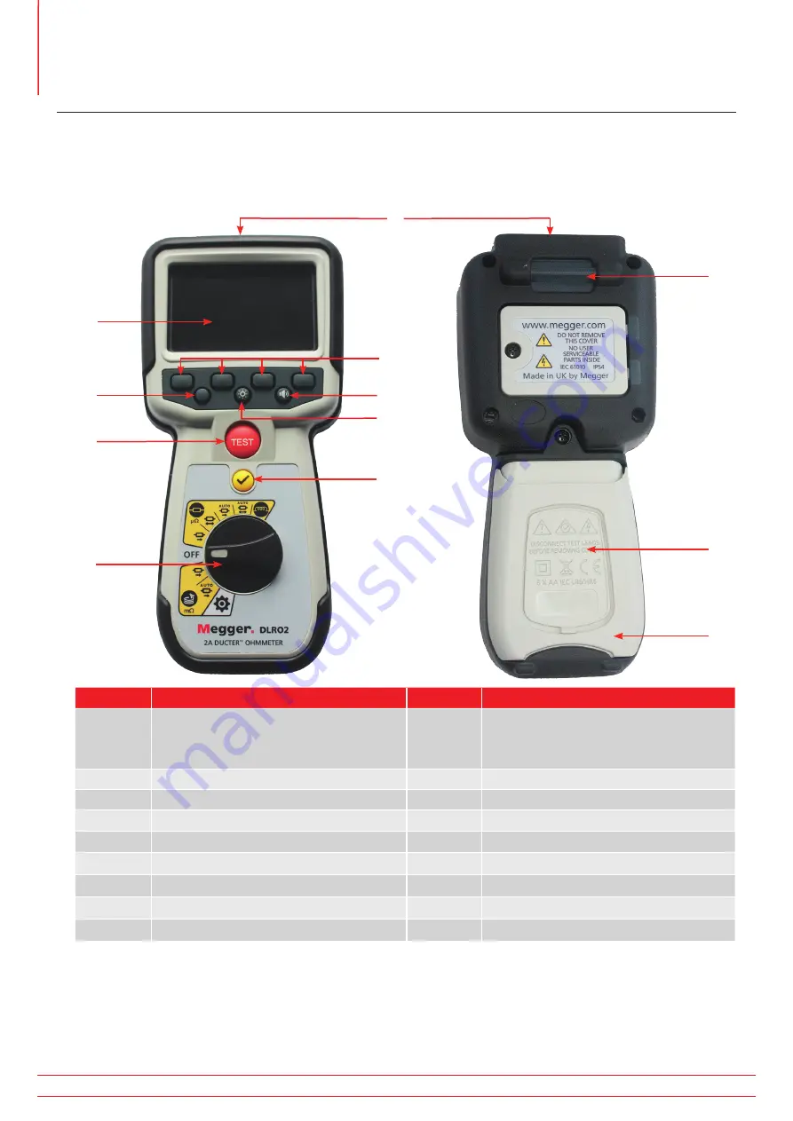
3.  Instrument Controls 

3.1   Instrument Layout

Front View 

Rear View

1

2

6

3

4
5

8

7

9

Item

Description

Item

Description

External electrical connections.   

Refer to 3.4.1 External electrical 
connections of DLRO2 on page 11

10

Attachment point for strap

Display 

11

Battery cover

Soft keys (multifunction) 

12

Stand

Has no function on this model 

Back-light control

Has no fucntion on this model

Test

TICK button

Rotary selection switch

11

10

12

Instrument Controls 

www.megger.com

DLRO2

8

Summary of Contents for Ducter DLRO2

Page 1: ...DLRO2 Ducter Low Resistance Ohmmeter 2 A User Guide ...

Page 2: ...the specification of its products from time to time without notice Although every effort is made to ensure the accuracy of the information contained within this document it is not warranted or represented by Megger Ltd to be a complete and up to date description For Patent information about this instrument refer to the following web site megger com patents www megger com DLRO2 ii ...

Page 3: ...ited described in this user guide is in compliance with Directives 2014 30 EU and 2014 35 EU where they apply The full text of Megger Instruments EU declarations of conformity are available at the following internet address megger com company about us eu dofc This manual supersedes all previous issues of this manual Please ensure that you are using the most recent issue of this document Destroy an...

Page 4: ...3 Instrument Controls 8 3 1 Instrument Layout 8 3 2 Instrument Display 9 3 3 Instrument Rotary Control 10 3 4 Instrument connections and leads 11 3 4 1 External electrical connections of DLRO2 11 3 5 The Difference Meter 12 3 5 1 Difference Meter example of operation 13 4 Setting up the DLRO2 15 4 1 Warnings and exception conditions 15 4 2 Power 15 4 2 1 First use 15 4 2 2 Turn the instrument on a...

Page 5: ...nditions 27 8 1 Error code categorization 27 8 2 On screen error messages 27 8 2 1 Error screen A 27 8 2 2 Fuse fail screen 27 8 2 3 Error screen B 27 9 Settings 28 9 1 General settings 28 9 2 Language settings 29 9 3 Instrument Information 29 9 4 Firmware update 29 10 Maintenance 31 10 1 General Maintenance 31 10 2 Cleaning 31 10 3 Battery 31 10 3 1 Battery status 31 10 3 2 12 V supply 32 10 3 3 ...

Page 6: ...13 Calibration Repair and Warranty 38 13 1 Return procedure 38 14 Decommissioning 39 14 1 WEEE Directive 39 14 2 Battery disposal 39 15 Notes 40 Contents www megger com DLRO2 vi ...

Page 7: ...Contents www megger com DLRO2 vii ...

Page 8: ... all DLOR2 variants Some facilities may not be available on your model of this equipment 1 2 Features New Difference Meter for quick comparison of results Refer to 3 5 The Difference Meter on page 12 Rotary dial test function selection Unidirectional or bidirectional test options on normal resistance test mode Secondary display field showing either forward and reverse measurement results or previo...

Page 9: ...ucture track high current joints signalling systems Marine Power wiring systems protection systems ship to shore bonding cathode protection system testing Cable laying applications Oil and gas pipelines Bonding between welded joints grounding systems Automotive and EV Battery connections weld quality quality of crimped connections assembly robot welding cables Cable manufacturers Quality control c...

Page 10: ... be issued via the Megger web site This may concern new accessories new usage instructions or a software update Please occasionally check on the Megger web site for anything applicable to your Megger instruments www megger com Introduction www megger com DLRO2 4 ...

Page 11: ...hese safety warnings must be read and understood before the instrument is used Retain for future reference Warning This instrument must be operated only by suitably trained and competent people Protection provided by the instrument may be impaired if it is not used in a manner specified by the manufacturer Local Health and Safety Legislation requires users of this equipment and their employers to ...

Page 12: ...lips must be in good order clean and with no broken or cracked insulation Verify the integrity of the test leads before use The safe maximum limit of a measurement connection is that of the lowest rated component in the measurement circuit formed by the instrument test leads and any accessories Ensure that hands remain behind finger guards of probes and clips 2 3 Test lead safety warnings Test lea...

Page 13: ... external voltage is applied between the terminals and the instrument is set to ON the external voltage warning will flash on the display This is a warning that the item under test is live it might be dangerous so testing is disabled The external voltage warning message will flash if more than 5 V potential difference is applied between the voltage terminals and the current terminals This warning ...

Page 14: ...ions Refer to 3 4 1 External electrical connections of DLRO2 on page 11 10 Attachment point for strap 2 Display 11 Battery cover 3 Soft keys multifunction 12 Stand 4 Has no function on this model 5 Back light control 6 Has no fucntion on this model 7 Test 8 TICK button 9 Rotary selection switch 11 10 12 Instrument Controls www megger com DLRO2 8 ...

Page 15: ...y indicator 3 Primary field 11 Soft keys functions dependant on rotary selection switch position 4 Latest result 12 Secondary field 5 Battery condition indicator 13 C continuity indicator 6 Noise indicator 14 Forward measurement result 7 Units of measure for latest result 15 Unidirectional or bidirectional selection 8 Reverse measurement result 16 Inductive charge warning Instrument Controls www m...

Page 16: ... Rotary Control Item Description Item Description Rotary switch positions 1 Inductive mode 4 Long leads mode 2 Resistance mode 5 Settings mode grey 3 Off position 3 2 5 4 1 Instrument Controls www megger com DLRO2 10 ...

Page 17: ... front Slider to back 1 7 2 1 7 4 6 Item Description Item Description 1 Rear attachment point for strap 4 Slider in rear position 2 Slider in front position 5 Battery charger connection 3 Connections C1 P1 P2 C2 6 USB port firmware update 7 Front 3 5 Instrument Controls www megger com DLRO2 11 ...

Page 18: ... Noisy results are shown with a red marker Good results are shown with a blue marker When testing pressing the TICK button sets the latest reading as the reference reading and cancels all other readings recorded on display including those on the Difference Meter and the secondary field 3 2 1 4 5 Item Description Item Description 1 Difference Meter 4 Blue result marker shows that noise is not prese...

Page 19: ...t is made the Difference Meter shows result relative to reference measurement 30 in this case showing an increase Shown as a blue ring Note For each successful measurement the needle leaves a blue marker on the Difference Meter a red marker if the reading contains noise Third measurement is made the Difference Meter shows it s result relative to the first 1000 in this case showing an increase The ...

Page 20: ...ote The units on the main display have changed back to µΩ and are shown in blue indicating another change Fifth measurement is made the Difference Meter shows it s result relative to the reference measurement This reading is now just 1 lower than the reference measurement Note The units remained unchanged as µΩ and are shown in black Instrument Controls www megger com DLRO2 14 ...

Page 21: ...ry Replacement on page 33 4 2 2 Turn the instrument on and off 1 Turn the instrument ON by rotating the rotary switch to the required operating mode away from the OFF position 2 Turn the instrument OFF by rotating the rotary switch to the OFF position 4 2 3 Battery options Caution Do not attempt to recharge alkaline cells this action is a high potential fire hazard The DLRO2 is powered by Internal...

Page 22: ...ved before any stored charge has been discharged at the end of the test Failure to comply with these instructions might result in an arc being produced which might be dangerous for the instrument and the operator 5 1 Manual stop 1 Turn rotary switch to select the inductive mode position 5 1 1 First test Inductive test screen appears Inductive Mode shows in secondary field for a short time then dis...

Page 23: ... be displayed during the pre charge phase of the measurement to be replaced by resistance and current values updating as the instrument auto ranges Readings continue to update until a stable measurement is achieved 2 When the result is stable press the TEST button The Difference Meter records the reading End of the test To stop the test press the TEST button Note The TICK button will set a new ref...

Page 24: ...ote Soft key 1 toggles MANUAL AUTO 2 Select AUTO on soft key 1 3 Connect C1 C2 and P1 P2 to the instrument and the unit under test C and P indicators show red background with for no continuity or green background with for good continuity Proceed when both show The continuity indicators are active during the test and will update if continuity is lost Tests Inductive mode www megger com DLRO2 18 ...

Page 25: ...ress the TEST button Previous result moves to secondary display Primary display shows 3 dashes till a new valid reading is received The readings will update until a stable measurement is achieved at which point the instrument will automatically stop the test The test can also be stopped at any time by pressing the TEST button After the test the Difference Meter records the reading and primary scre...

Page 26: ...position OR Resistance test screen appears Auto start Bidirectional Resistance Mode or Auto start Unidirectional Resistance Mode shows in secondary field for a short time then disappears Note Soft key 1 toggles continuous single test Soft keys 2 3 cycles through current ratings default is 2 A selectable 1 A 100 mA 10 mA 1 mA In bidirectional soft key 4 toggles between Display previous 2 results an...

Page 27: ...inuity was maintained This indicates the C or P lead must be disconnected and reconnected to restart the test Note Test button will start another test Soft key 1 toggles continuous single test Soft keys 2 3 cycles through current ratings default is 2 A selectable 1 A 100 mA 10 mA 1 mA Soft key 4 is inactive TICK button sets new reference value 6 1 2 Post auto start bidirectional test After an auto...

Page 28: ...ctable 1 A 100 mA 10 mA 1 mA Soft key 4 is only active in bidirectional resistance mode and toggles between Display previous 2 results Forward and reverse direction In unidirectional resistance mode soft key 4 is inactive and will default to Display previous 2 results 2 Select test settings using the soft keys 3 Connect C1 C2 and P1 P2 to the instrument and the unit under test C and P indicators s...

Page 29: ...he soft keys will not operate during this test 6 2 3 After the test For a single test the result is displayed constant in the main field To perform another test press the TEST button continuity indicators must be green Note Soft key 1 toggles continuous single test Soft keys 2 3 cycles through current ratings default is 2 A selectable 1 A 100 mA 10 mA 1 mA Soft key 4 is only active in bidirectiona...

Page 30: ...s displayed 7 1 Long leads mode auto and manual start 1 Turn rotary switch to select the long leads mode either MANUAL or AUTO position OR Long leads test screen appears either Long Leads Mode Manual Start or Long Leads Mode Auto Start will show in the secondary field for a short time the text then disappears to reveal the previous results fields 2 Connect C1 C2 and P1 P2 to the instrument and the...

Page 31: ...ned pressing the TEST button will start a new test 7 1 2 For auto mode In auto start mode the instrument will start the test when continuity is established If both C and P continuity is made before the test mode is selected the continuity flags will be shown in grey this means that the user must disconnect and reconnect or press the TEST button to start the test During the test continuity indicato...

Page 32: ...ts appear in the secondary fields left is the previous result and right is the result before that For auto single tests the continuity indicators are grey indicating that to repeat the test the leads must be disconnected and reconnected again If the test has been stopped by the TEST button the continuity indicators will be grey If continuity already is shown on the C and P connectors press the TES...

Page 33: ...s No user intervention 8 2 On screen error messages 8 2 1 Error screen A 1 Error code 2 Error text where applicable explains what went wrong Remove the message by pressing the TICK button 8 2 2 Fuse fail screen 1 Error code 2 Error text fuse failure The fuses in DLRO2 are not user replaceable If this error screen appears the instrument must be returned to Megger for repair Refer to 13 Calibration ...

Page 34: ...gle between yellow and white using the tick button Backlight Timer Use soft keys 2 and 3 to select from off up to 60 seconds default is 20 seconds Battery Technology Toggle between NiMH and alkaline using the tick button Difference Meter Toggle ON and OFF using the tick button Sleep Timer Press the tick button and navigate using soft keys 2 and 3 Use the tick button to set Restore Factory Settings...

Page 35: ...tion and product serial number 9 4 Firmware update The USB port on top of the DLRO2 is for firmware updates only There are two parts to a firmware update the first part updates the user interface while the second part updates the measurement firmware A firmware update file may include either or both of these Connect a USB flash drive to the DLRO2 with the firmware update file in the root directory...

Page 36: ...tart the DLRO2 turn off and on 7 If a measurement firmware update is to be performed then the measurement firmware update screen will display At the end of the firmware update the instrument will automatically restart Settings www megger com DLRO2 30 ...

Page 37: ...ity and longevity of the installed batteries Ensure if using rechargeable batteries they are fully charged before use charger supplied Store batteries in a cool dry place Batteries can be damaged when exposed to heat 10 3 1 Battery status Warning Do not recharge Alkaline batteries The battery condition icon is positioned at the top right hand corner of display This icon is displayed at all times w...

Page 38: ... is fully charged the screen will display a solid green battery Battery charging Battery fully charged When charging the DLRO2 while the instrument is ON an animated battery will display in the top right hand corner of the screen Tests cannot be performed while the charger is connected If the TEST button in pressed the buzzer will sound However the Settings are fully accessible while the instrumen...

Page 39: ...moving the battery cover Caution Batteries should not be left in the instrument if remaining unused for an extended period 1 2 4 3 No Description Quantity 1 Screw captive 1 2 Cover battery 1 3 Battery isolation tab 1 4 Batteries 6 Maintenance www megger com DLRO2 33 ...

Page 40: ... centred at the top of the cover 3 Battery cover 2 will now lift away from the top 4 Ease out of lugs at the bottom of the cover 5 The six batteries 4 can now be lifted out of the compartment Caution Ensure the new cells are replaced in the correct polarity as indicated on the cells and battery compartment Caution Ensure all batteries are of the same type do not mix NiMH or Alkaline 6 Replace all ...

Page 41: ...mode Resistance of inductive loads Overall resistance range 1 μΩ 2000 Ω Max resistance across C terminals 2 A with up to 1 1 Ω total resistance and 1 A with up to 3 2 Ω total resistance Basic accuracy Bi directional test current mode 1 2 digits Uni directional test current mode 1 10 digits Inductive mode or unidirectional mode will introduce an undefined error if an external EMF is present Resista...

Page 42: ...de Operational to 3000 m Temperature Operational range 0 ºC to 50 ºC Storage range 20 ºC to 50 ºC Humidity Operational to 95 Storage to 90 POWER SUPPLY Rechargeable 6 x HR6 Ni MH batteries with in unit fast charge also ability to use non rechargeable Alkaline AA batteries LR6 Battery charge time 4 hours Battery life 1000 bi directional tests at 2 A into a 1 Ω load BATTERY CHARGER ADAPTOR Mains lin...

Page 43: ...ck with user guide Hanging hook and strap 1012 068 Soft pouch 1012 063 12 2 Optional Accessories Item Order No Test leads Set of 4 Kelvin probe pins Replacement probe tips 1012 064 4 right angled adaptors to allow hook terminated E g KC100 leads to fit DLRO2 1012 511 10 A Fused test probe and clip lead set 1013 224 DLRO2 current and potential leadset 2m 2 x red lead 2 x blk lead 2 x grabber clip 2...

Page 44: ...vided to enable the Service Department to prepare in advance for receipt of your instrument and to provide the best possible service to you Model for example DLRO2 Serial number found on the display under settings device information or on the rear cover and by the batteries or on the calibration certificate Reason for return for example calibration required or repair Details of the fault if the in...

Page 45: ...al Megger website 14 2 Battery disposal The crossed out wheeled bin symbol placed on a battery is a reminder not to dispose of batteries with general waste when they reach the end of their usable life The battery is located under the battery cover on the back of the instrument To remove the battery follow the instructions in 10 4 Battery Replacement on page 33 For disposal of batteries in other pa...

Page 46: ...Notes www megger com DLRO2 40 15 Notes ...

Page 47: ... TX 75237 USA T 800 723 2861 USA only T 1 214 333 3201 F 1 214 331 7399 E USsales megger com Megger AB Rinkebyvägen 19 Box 724 SE 182 17 DANDERYD T 46 08 510 195 00 E seinfo megger com Megger USA Fort Collins 4812 McMurry Avenue Suite 100 Fort Collins CO 80525 USA T 1 970 282 1200 Manufacturing sites Local Sales office This instrument is manufactured in the United Kingdom The company reserves the ...

Reviews: