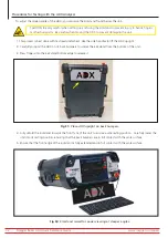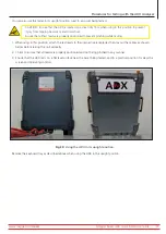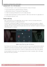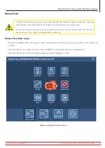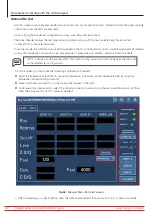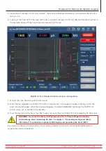
2. If you choose to run capacitance testing, the software will alert you to reconfigure the test leads as shown in the
example below.
3. Test Lead 1 will be connected to motor lead 1, test lead 2 to the motor frame, and test lead three will be
disconnected (not contacting any motor lead or ground).
Fig 43:
Manual Test; lead reconfiguring message for capacitance testing.
4. Another message will appear after the capacitance test completes telling you to restore the test leads to their
original connections.
Ensure that the connections are restored before clicking OK
.
5. The RLC test registers the measurements taken on each test lead and compares them to the target values specified
in the Test Configuration. If the measured values are within specified limits, the test will pass. The test also checks
for imbalance between the phases and displays results in the RLC TEST tab.
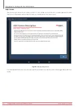
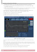
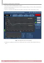
6. When the RLC testing completes, you will see measurement results displayed in the RLC TEST tab as shown in the
example below. Failing tests will appear in red. Examine the results to start your assessment of the problem for
failed tests.
Fig 44:
Manual Test—RLC main test results tab.
www.megger.com/baker
Megger Baker ADX Quick Reference Guide
43
Procedures for Testing with the ADX Analyzer


