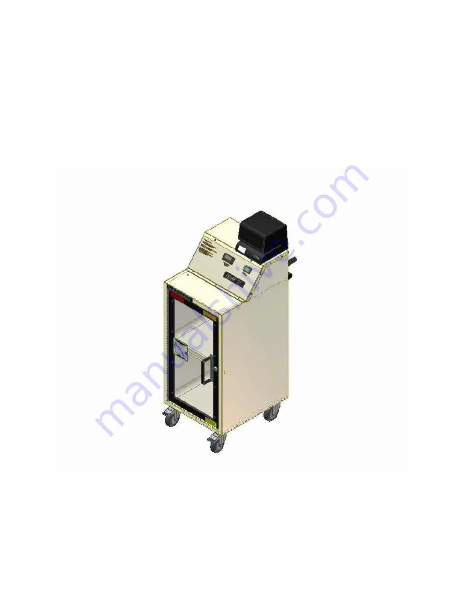
5640.A
TEMP 2
FLUID WARMER
OPERATORS MANUAL
6000 Series
Medical Solutions, Inc
3901 Centerview Drive, Suite L
Chantilly, VA 20151
800-435-7600
703-834-0039 (Fax)
Page 1: ...5640 A TEMP 2 FLUID WARMER OPERATORS MANUAL 6000 Series Medical Solutions Inc 3901 Centerview Drive Suite L Chantilly VA 20151 800 435 7600 703 834 0039 Fax ...
Page 2: ...perature of the top shelf heater plate The bottom display number in green will indicate the temperature of the bottom shelf heater plate During the time that the controller is directing the unit to warm a light will illuminate in the upper left corner of the display The Documentor is designed to assist in the compliance with JCAHO standard MM 2 20 and the fluid manufacturer s specifications for ti...
Page 3: ...onditions Storage Temperature 40º to 80º C 40º to 176º F Humidity Conditions 0 to 90 up to 40º C non condensing Ambient Operating Temperature 10º to 55º C 14 to 131º F Atmospheric Pressure During Minimum of 16 288 in Hg Transporting Electrical Requirements Power Requirements 110 120 VAC 60 HZ Fusing 2 each 5 Amps Mains 2 each 3 Amps Heaters 2 each 0 5 Amps Documentor Outlet Amperage Consumed 4 Amp...
Page 4: ...cle located on the back of the TEMP 2 6 Move the TEMP 2 to the desired location check that power switch is off and plug the power cord into an approved outlet Documentor Instructions 1 Prior to loading the cabinet with bags use the Documentor to label the bags with a future date that follows the manufacturer s recommendation for the length of time a bag is to be warmed Future Date Label To create ...
Page 5: ...below TO CHANGE THE SET POINT PRESS THE INDEX KEY LEFT MOST KEY TO VIEW SET POINT ONE SP1 TOP SHELF PRESS THE INDEX KEY TWICE LEFT MOST KEY TO VIEW SET POINT TWO SP2 BOTTOM SHELF PRESS THE UP OR DOWN ARROW KEYS TO CHANGE THE SET POINT PRESS THE ENTER KEY RIGHT MOST KEY TO ACCEPT NEW SET POINT PRESS THE INDEX KEY 3 The shelves will operate independently from each other When one shelf is not in use ...
Page 6: ...t button the small digits on the left representing the year will flash 13 Tap the left button until the desired number appears then Tap the right button The digits representing the month should flash 14 Tap the left button until the desired number appears then Tap the right button The digits representing the day should flash 15 Tap the left button until the desired number appears then Tap the righ...
Page 7: ...er to the unit and refer to qualified service personnel Remove the service panel qualified person and remove any liquid and or dry components Perform any necessary hospital electrical safety checks before returning the TEMP 2 to service Trouble Shooting 1 If the unit fails to warm check the following a Check to see that the TEMP 2 is plugged in and the power switch is on b Check the set point sett...
Page 8: ...5640 A 8 Service Panel Location and Removal Remove the top plate to access the electrical compartment ...
Page 9: ...5640 A 9 Fuse removal instructions ...
Page 10: ...tted time compare the temperature reading on the controller to the temperature reading on the Fluke Thermometer the two temperatures should be within two degrees Fahrenheit of each other If the two temperature readings are within two degrees Fahrenheit of each other the temperature controller has been verified If they are not please contact Medical Solutions Inc at 800 435 7600 Repeat the calibrat...
Page 11: ... CONSEQUENTIAL OR OTHER DAMAGES INCLUDING BUT NOT LIMITED TO LOST PROFITS To enable MSI to administer the Warranty properly Buyer shall 1 register the Warranty using the form provided below and 2 promptly notify MSI of any claim hereunder As a condition to the Warranty Buyer shall use and maintain the Equipment according to the provisions of the Operator s service manual IMPORTANT THIS IS YOUR TEM...