MediaSonic MS9000 User Manual Download Page 38

HD Player 

Chapter 4: The Log/ File Information Windows 


36


Rev. 6.4 


• 

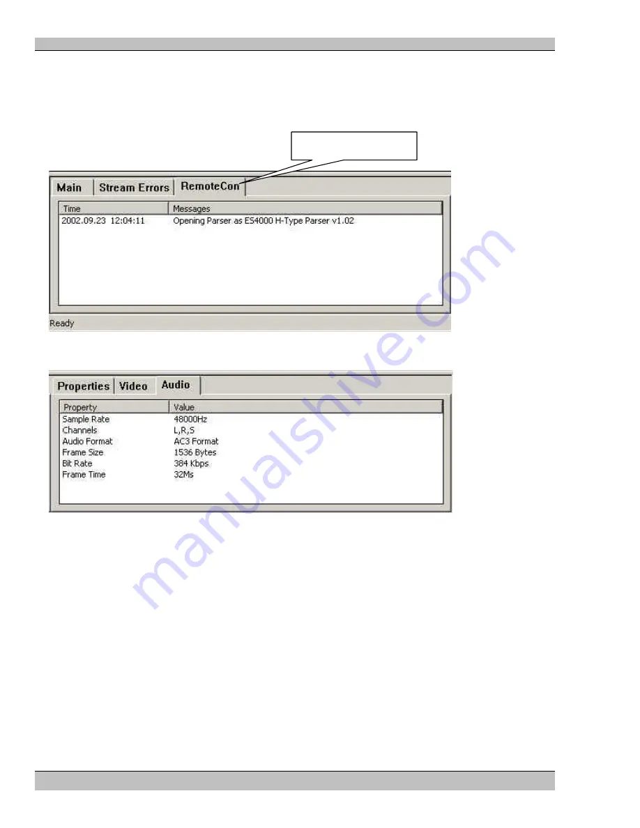
Stream Errors – Lists any errors in the MPEG stream, useful for troubleshooting. 

• 

Text Command Protocol (User Defined) –  This is a remote control connection through server Port 23. A 
log tab “RemoteCon” for example is created for each remote control method defined by the user. These 
tabs display any commands received by that method and will also show any protocol errors encountered. 
(See Chapter 11: Remote Control Configurations, also, Chapter 12: Remote Control Protocols) 


The File Information Window 


The File Information Window displays various properties unique to the current clip: 

• 

Properties – Data Rate of the clip 

• 

Video – Horizontal and Vertical Resolution, Frame Rate and PID 

• 

Audio – Sample Rate, Channels, Format, Bit Rate and Frame Time 

Click the appropriate tab to view the page contents. 

User Defined Tab 

Summary of Contents for MS9000

Page 1: ...User Guide MS9100P MS9100D MS9200P MS9000 HD Player Control Application Software...

Page 2: ...y kind either directly or indirectly and is subject to change without prior written notice Electrosonic Media Networks its employees or appointed representatives will not be held responsible for any d...

Page 3: ...of common menus and commands necessary for operation of a personal computer The manual is comprised of the following chapters Chapter 1 Introduction Quick Reference Guide Chapter 2 The Playlist Displa...

Page 4: ...ower information 6 3 06 25 04 SS Update Command Reference 6 4 04 18 05 SS Update Command Reference Trademarks MEDIASONIC MS and the MEDIASONIC logo are registered trademarks of ELECTROSONIC Ltd ELECTR...

Page 5: ...d 16 MS9200P MS9100P Rack mounted players 16 MS9100D Desktop player 16 The Windows Media Player 16 To start the Media Player 16 To play a different clip 17 The MediaSonic MS9000 HD Player Control Appl...

Page 6: ...oop 33 Audio Output 33 Video Output Black 34 Video Output 34 Color Bars 34 Fast Forward Loop Slider 34 Confidence Display 34 Chapter 4 The Log File Information Windows 35 The Log Window 35 The File In...

Page 7: ...Edged System 51 Vertical and Horizontal Borders 53 Gamma 54 Black Correction 56 Update 57 Chapter 8 Genlock 58 Genlock Mode 58 Genlock Standalone Master 59 Genlock ES Gen 59 Genlock Cable 60 Genlock...

Page 8: ...00 81 Available Player Commands 82 Chapter 13 Video Outputs 83 The PCI HD Decoder Card Interfaces 83 Primary Output MS9200P MS9100P MS9100D 83 Secondary Output MS9200P 83 HDSDI MS9200P 84 Chapter 14 A...

Page 9: ...Example 2 Unsuccessful Pings 96 Appendix B An Introduction to MPEG 97 Digital and Compression Video 97 What is MPEG 97 I B and P frames 98 Groups Of Pictures GOP 98 Multiplexes And Elementary Streams...

Page 10: ......

Page 11: ...This powerful control interface allows easy access to all of the Player s basic as well as advanced functions Support for a wide range of remote control options using serial RS232 or Ethernet TCP IP i...

Page 12: ...he HD Player hard disk Remote Control COMM Port See Chapters 11 and 12 Timecode In Out See Chapter 6 MS9100D must use optional MS9000 HD Player Software Genlock In out Composite Black Burst See Chapte...

Page 13: ...outputs SPDIF 5 1 audio output Playback using the MediaSonic MS9000 HD Player Control Application software Windows MediaPlayer support included Support for Soft Edging of images Rack mounted enclosur...

Page 14: ...HD Player Chapter 1 Introduction Quick Reference Guide 12 Rev 6 4 Figure 2 MS9200P Digital HD Player Card Output Detail...

Page 15: ...oftware Windows MediaPlayer support included Rack mounted enclosure Composite Video Black Burst synchronization DECODER CARD ANALOG MS9100 ANALOG AUDIO OUT TO HD DISPLAY SPDIF OUT 5 1 AUDIO REF IN COM...

Page 16: ...pplication software Figure 4 MS9100D Analog HD Player Desktop model connections WARNING Ensure that the AC Input Power Supply Switch located on the back of the 9100D HD Player is set to the same volta...

Page 17: ...g HD Player AC Power Input Voltage Selector Switch location Although every effort has been made at our factory to make sure that the switch is set correctly before shipping to a particular geographic...

Page 18: ...MediaSonic HD Player Control Application software is available at an additional cost The Windows Media Player The quickest way to verify your system set up is to view a video clip with the included Me...

Page 19: ...IDEO FILES folder if it has been used with MPEG files previously If not you may have to browse to the VIDEO FILES folder and double click the VIDEO FILES folder in the Open window Select the file you...

Page 20: ...p multi projector displays including adjustments for Gamma and Black Correction Control other HD Players as well as itself in a Timecode Master Slave system Remote control your system with commands fr...

Page 21: ...nts will be discussed in greater detail in the relevant chapters To Load a Clip 1 Open a Windows Explorer window 2 Select the MPEG file clip you wish to play 3 Drag the file onto the Playlist in the H...

Page 22: ...he clip The MediaSonic HD Player Main Menu Use the Main Menu as in any Windows software The Main Menu allows access to many basic functions of the HD Player The File Menu The HD Player utilizes the vs...

Page 23: ...the main drop down menus The display changes as you drag your pointer along the menu options Turn on the Driver Statistics window The Driver Statistics window is used for information only The Configu...

Page 24: ...HD Player Chapter 1 Introduction Quick Reference Guide 22 Rev 6 4 The About HD Player display Click here to Close...

Page 25: ...e HD Decoder Configuration window From the Start menu select Programs MediaSonic HD Decoder Configuration as shown in the following graphic The following dialog appears as part of the HD Decoder Confi...

Page 26: ...he default mode Choose SPDIF Audio for 5 1 surround sound or No Audio if required Note Stereo Audio makes use of the player s sound card audio output 5 1 surround sound is available at the SPDIF conne...

Page 27: ...HD Player Chapter 1 Introduction Quick Reference Guide 25 Rev 6 4 Update Select the Update button to save your settings after you have made any changes...

Page 28: ......

Page 29: ...specific configurations The Channel Properties Dialog This dialog controls system configurations The functions of these dialogs will be described in detail later in this manual Note After Editing the...

Page 30: ...s will be placed You may re order clips in the Playlist at any time simply drag files to different positions within the Playlist as necessary The Clip Properties Dialog The Clip Properties dialog box...

Page 31: ...tion and name of the MPEG transport file Click the Browse button to display a standard file selection window that can be used to locate the required file Timecode This section provides a number of con...

Page 32: ...you wish to play 2 Click the Cue button on the Transport 3 Click the Play button on the Transport to begin Selecting and Playing a List Sequence 1 Drag a Pointer at the left of the Playlist to the beg...

Page 33: ...us display is linked to the Transport Controls and shows various pieces of useful information about the current state of the HD Player Transport status The transport status shows the current operating...

Page 34: ...nd is received the MPEG decoder is primed and ready to play This is essential in multi channel systems where a predictable startup is a requirement Playing The playing indicator will be displayed whil...

Page 35: ...owever affect the primary secondary and HDSDI outputs Aud This indicator will be on if the audio output is active It will be off when the audio is muted Audio mute will mute both the SPDIF and Stereo...

Page 36: ...output Video Output This button is used to activate the Video output following either a video mute or color bars command Color Bars This button is used to display color bars on the video outputs Fast...

Page 37: ...unning The information shown can be used to debug show control programming problems check communications protocols and generally monitor the condition of the HD Player The Log display is arranged as a...

Page 38: ...er These tabs display any commands received by that method and will also show any protocol errors encountered See Chapter 11 Remote Control Configurations also Chapter 12 Remote Control Protocols The...

Page 39: ...ion about the main menu commands Use the Status Bar for quick tips about the commands available on the main drop down menus The display changes as you drag your pointer along the menu options To turn...

Page 40: ...features that are set once and not changed as part of the show control system To Modify the Player Configuration Right Click the Playlist area and select Channel Properties from the drop down menu The...

Page 41: ...e Configuration files section of this manual Video on at startup Select this option to enable HD Video output when the HD Player is powered on This option will usually be set but can be useful in cert...

Page 42: ...Players Default is 1 Enter the appropriate Base Channel Number into the Text Command Protocol command structure refer to Chapter 12 Remote Control Protocols for more information Audio Output Format Th...

Page 43: ...he genlock master in a multi channel HD Player system Genlock ES Gen MS9200P only Select this mode when using the HD Player with a proprietary Electrosonic genlock feed referred to as ES Gen This sign...

Page 44: ...e seen on the GUI confidence display The video Output Format field tells the HD Player how to format the video output Normally this will match the contents of the file A file encoded as 1080i is norma...

Page 45: ...720p 48 Hz 50Hz 59 94 Hz 60 Hz Commonly referred to as 720p 720x480p 48 Hz 50Hz 59 94 Hz 60 Hz Commonly referred to as 480p 960x72op 59 94 Hz 1024x768p 59 94 Hz This mode was designed to match the res...

Page 46: ...ncorporate a device that generates the timecode for the system referred to as the master timecode This signal is distributed to each timecode aware device in the system These are often referred to as...

Page 47: ...ommand is received after the clip a cued If the Play At see below option is not enabled this will also be the point when video output begins The HD Player will output this timecode as a Jam Sync signa...

Page 48: ...timecode while the clip is still playing or extend the timecode after the clip has ended The following examples show some typical uses of the timecode generation options Generate a timecode starting a...

Page 49: ...in the properties to set the parameters Play At The Play At box is used to set the trigger point at which the cued file will begin playing Loop Input to Output Select this option to pass incoming tim...

Page 50: ...also be used as a simple timecode reader if verification of incoming timecode is necessary Simply select the Receive mode but do not check the Play At option In this mode the Timecode window will sho...

Page 51: ...single image on a screen when using multiple projectors This results in a seamless display that shows no signs of being made up of spliced together images from separate projectors A soft edged display...

Page 52: ...nt is termed Soft Edging control and provides electronic manipulation of the image in both the horizontal and vertical axis Note 1 Soft Edging is available only on the Secondary analog HD2 and HDSDI o...

Page 53: ...verlap 51 Rev 6 4 Configuring a Soft Edged System To access the Soft Edging control right click anywhere in the Playlist window Select Channel Properties from the drop down menu In the Channel Propert...

Page 54: ...HD Player Chapter 7 Soft Edging Display Overlap 52 Rev 6 4 This will open the Overlap Control Dialog box The following sections describe the various parameters that can be controlled Soft Edge Control...

Page 55: ...255 in both horizontal and vertical axes If both borders in an axis are used they must be set identically The following example shows settings for the center screen of the 3 x 1 projection system show...

Page 56: ...In its simplest form this ramp is linear gamma value of 1 0 as illustrated above However the light output of a projector does not have a linear relationship to input voltage and so a gamma correction...

Page 57: ...values 1 6 2 8 although this will vary depending upon the projector lamp used The actual value will be determined during projector alignment The following example shows a Luma and Chroma gamma setting...

Page 58: ...ignal brightness must first be elevated using the Brightness control as described in the BCS section This ensures an amount of headroom for the black level to work within Note The Contrast setting may...

Page 59: ...hese settings at any time during the adjustment of the Gamma and Overlap parameters A picture disturbance will be observed while the update is in progress a normal picture will resume after the settin...

Page 60: ...o is decoded across multiple Players at the same time Note MS9200P ESGen Genlock and or Composite Video Black Burst sync available MS9100P Composite Video Black Burst sync available only MS9100D Compo...

Page 61: ...ilable We recommend that this system of Genlock be restricted to a maximum of 4 HD Players in a daisy chain To set up an ES Gen system 1 Set the Master HD Player in Genlock Standalone Master mode 2 Se...

Page 62: ...tandard selected For example it is not possible for the HD Player to Genlock to a PAL composite signal if the output mode is set for a 60Hz output mode Typically all HD Video Players in the same syste...

Page 63: ...drag it to the left or right Any changes to the settings will take effect immediately on the various video outputs The adjustments are as follows Brightness Brightness affects the intensity of the vi...

Page 64: ...h while a highly saturated red is bright and punchy It is important not to confuse saturation with brightness Saturation can be thought of as the amount of pigment in a color Dragging the bar to the l...

Page 65: ...yer will automatically load the last configuration file used when the unit is switched on Saving the current configuration The current configuration can be saved using the Save As command Click File S...

Page 66: ...ev 6 4 Or press Ctrl S on the keyboard Loading a configuration file A different configuration can be loaded into the HD Player using the load command To load a configuration file Click File Open from...

Page 67: ...Remote Control Methods wizard This can be reached from the configuration menu as illustrated below Click on Configurations Remote Control Configurations in the main menu to display the Remote Control...

Page 68: ...tion since it cannot be undone The following sections describe each page of the wizard The Remote Control Wizard Method Type dialog The first screen in the wizard requires two pieces of information th...

Page 69: ...600 19200 57600 115200 Parity Odd Even or None Stop bits 1 or 2 stop bits To modify the Serial Control Parameters Click the arrow buttons adjacent to the appropriate boxes and select the necessary set...

Page 70: ...HD Player Chapter 11 Remote Control Configuration 68 Rev 6 4 Click on the list to select either Protocol Click Next to advance Click Finish to end This will return you to the Remote Control Methods...

Page 71: ...safe to select ports above the value 2000 although any number can be used in a closed installation 1 Enter the port number in the window NOTE When using ESCAN for control set Port to 4000 and select M...

Page 72: ...or DCD RXD TXD DTR SG DSR RTS CTS RI 9 WAY D TYPE PLUG FRONT VIEW 1 5 6 9 Figure 6 Serial Port Pin Functions RJ45 Ethernet This is a 100 Base T connection that supports the TCP IP protocol RJ45 Pinout...

Page 73: ...r should be set to 1 in the single channel version unless it has been changed using the Base Channel Number setting in the Channel Properties window Command Structure The basic structure for a telnet...

Page 74: ...t This command requests the number of channels present on the player The player will respond with ChannelCount number SetOutputMode channel string This command is used to set the output mode for the p...

Page 75: ...for the player String is taken from the resolution table and must be a valid return option from the GetOutputResolution command Number is taken from the frequency table and must be a valid frequency f...

Page 76: ...hows an example response from the player MediaBranch 1 2 3 4 e MediaBranch 1 2 3 4 e exhibit MediaBranch 1 2 3 4 e exhibit mainshow MediaBranch 1 2 3 4 e exhibit grids MediaBranch 5 6 7 8 f MediaBranc...

Page 77: ...Playlist AddPlaylist string1 mediapath clip Adds a clip identified by clip located in the media path identified by mediapath to the playlist identified by string1 The Player will respond with OK or E...

Page 78: ...The Playrange command requires an amount of time to complete because of some initialization that must occur when a new file is selected The status commands can be used to poll the player to find out...

Page 79: ...l respond with OK channel X playing or ERROR Stop Channel list Stops the currently playing file and turn video off The Player will respond with OK channel X paused or ERROR Pause Channel list Pauses t...

Page 80: ...n video for the requested channel The Player will respond with OK or ERROR Videooff Channel list Turn off Mute video on the required channel The Player will respond with OK or ERROR Videobars Channel...

Page 81: ...mmand Timecode Commands Tcgenerate Channel list timecode Turns the timecode generator on and sends the timecode hh mm ss ff out as a jam sync The Player will respond with OK or ERROR Tcreceive Channel...

Page 82: ...Play the currently loaded file When a file is playing the HD player will return this command Channel x Playing cr lf where x is the base channel set in the channel properties When a file has played t...

Page 83: ...marker 01 Hex This single byte value indicates the start of a message H message type indicator 48 Hex This single byte value indicates the ES4000 message type FrameNo Chapter frame No This field is a...

Page 84: ...e Mode 83 Audio On 84 Audio Off A2 Set stop point for play list FrameNo last file to play in playlist To use the ES400 protocol to control the HD Player the following steps should be performed Set up...

Page 85: ...9200P only The PCI HD Decoder Card Interfaces The following figure shows the PCI Decoder card interface DECODER CARD DIGITAL MS9200 EXTENDER CARD MS9200 HD 1 HDSDI HD 2 OUT IN ES GENLOCK CVBS SPDIF IN...

Page 86: ...blending 1 255 pixels lines HDSDI MS9200P This is a digital output conforming to the SMPTE292M specification It is output on the BNC connector Currently it supports 1920 x 1080 and 1280 x 720 resoluti...

Page 87: ...ost systems will use a Genlock signal that will be either 29 97Hz or 25Hz it is necessary that the frame rate of the content also be one of these frequencies Genlock The genlock features in the HD Pla...

Page 88: ...up a system using this method is to common the RS232 receive lines on all the HD Players to the transmit signal of the RS232 port on the show control system After the Play command is received the Pla...

Page 89: ...Chapter 12 Remote Control Protocols and Appendix A TCP IP Communications HD Player 1 functions as Master to generate a triggering timecode and Genlock signal for the entire system Time code and Genloc...

Page 90: ...to Chapter 5 HD Player Configuration for more information on how to set the Base channel Device 1 Master Device 2 Slave Playrange 1 0 0 cr Playrange 1 0 0 cr Tcgenerate 1 cr Tcreceive 1 cr Tcplayat 1...

Page 91: ...HD Player Chapter 14 Application Notes 89 Rev 6 4...

Page 92: ...nts a three channel display The top HD Player is used to generate a triggering timecode for the entire system This timecode is looped through the middle unit using the loop through mode and finally se...

Page 93: ...etwork on a single port Messages transmitted in packets as network traffic allows Each device in the network has a unique address ensuring that a data message goes only to the specified device Maximum...

Page 94: ...r value but have a unique host identifier For example the following two IP addresses could exist on the same network 208 132 180 40 208 132 180 55 This assumes that 208 132 180 is the network identifi...

Page 95: ...ayer will be delivered pre configured with a class C IP address from the 192 0 0 family Remember that there are two rules for choosing IP addresses The network identifier must be the same for each add...

Page 96: ...ing the Network Dialog Box The HD Player s IP address is located in the Network dialog box which can be accessed in the following manner Right Click the Network Neighborhood desktop shortcut and then...

Page 97: ...the desired IP address in the IP Address field Saving the Subnet Mask and IP Address Values After setting the Subnet Mask and IP address Click on the OK button to save the values Note You must now re...

Page 98: ...e value may vary according to network traffic Example 2 Unsuccessful Pings If you are not successful pinging the address you will get one of two messages The message returned will indicate the type of...

Page 99: ...Compression Compression falls into two basic types Loss less and Lossy As the name implies loss less compression is able to recreate the original digital data exactly Lossy compression uses informati...

Page 100: ...eam I frames These are frames that contain a complete Image I frames act as the random access points into the video stream P Frames These frames contain only the differences from the previous frame B...

Page 101: ...PTSs in the PES packets It is important to understand that the PES times are features of Multiplexing audio and video into single streams They are not included in elementary streams Playback of elemen...

Page 102: ...bit errors in the stream The transport stream can contain any number of different audio and video stream pairs Transport streams were designed for the Television broadcast industry where errors may b...

Page 103: ...ar resolutions supported are 1920 x 1080 x 59 94 interlace and 1280 x 720 x 59 94 progressive Recommended Video PID numbers are 17 33 49 Audio PID numbers are video PID 3 Try to ensure that all files...

Page 104: ...c Ground 3 Blue Pb 11 No Connect 4 No Connect 12 No Connect 5 No Connect 13 H Sync 6 Red Ground 14 V Sync 7 Green Ground 15 No Connect 8 Blue Ground Secondary Video Output Format RGBHV YPrPb to SMPTE2...

Page 105: ...Pin Number Name 1 Red 9 No Connect 2 Green 10 Sync Ground 3 Blue 11 No Connect 4 No Connect 12 No Connect 5 No Connect 13 H Sync 6 Red Ground 14 V Sync 7 Green Ground 15 No Connect 8 Blue Ground Netwo...

Page 106: ...Formats SMPTE274M SMPTE296M Aspect Ratio 16 9 4 3 5 4 1920 x 1080i 1280 x 1024i 1280 x 720p 1024 x 768p 720 x 480p Video Outputs Electrical Analogue Output Color Space Support SMPTE 170M SMPTE 240M IT...

Page 107: ...Input Connector Phono Socket o Input Impedance 600 ohms o Input Level 100mV p p Timecode Output o SMPTE EBU Film 24fps o Output Connector Phono Socket o Output Impedance 600 ohms o Output Level 1V p...

Page 108: ...s lead to the frequent use of wide screen to refer to an HDTV display Baud A unit of signaling speed equal to the number of signal events per second Baud is equivalent to bits per second in cases wher...

Page 109: ...st under 1 Mbyte of storage 701 kbytes for 525 lines 829 kbytes for 625 lines HDTV frames are 4 5 times larger Digital film frames may be that much larger again CBR Constant bit rate CBR refers to the...

Page 110: ...n critical data Lossy Pictures are analyzed looking for redundancy and repetition and so discard unnecessary data The techniques were primarily developed for digital transmission but have been adopted...

Page 111: ...nion of MediaSonic that that 480 line progressive is not an HDTV format but does provide better resolution than 480 line interlace making it an enhanced definition format Huffman coding This compresse...

Page 112: ...ox Lossless compression Reducing the bandwidth required for transmission of a given data rate without loss of any data Lossy compression Reducing the total data rate by discarding data that is not cri...

Page 113: ...complex and not perfect MPEG coding However MPEG Splicers are beginning to appear to alleviate this difficulty Of the five profiles and four levels creating a grid of 20 possible combinations 11 have...

Page 114: ...sk errors or failures can be detected and corrected A series of RAID configurations is defined by levels and being designed by computer engineers they start counting from zero Different levels are sui...

Page 115: ...optional additional signal lines RS 422 is widely used for control links around production and post areas for a range of equipment Sampling Process by which an analog signal is measured often millions...

Page 116: ...he standard 75 ohm BNC connector and coax cable as is commonly used for analog video and can transmit the signal over 600 feet 200 meters depending on cable type Slice A series of macroblocks A slice...

Page 117: ...normal For example TV s normal aspect ratio is 4 3 and widescreen is 16 9 Although this is the aspect ratio used by HDTV widescreen is also used with normal definition systems YUV A color model used c...

Page 118: ...y The sampling frequency of Y is 13 5 MHz and that of R Y and B Y is each 6 75 MHz providing a maximum color bandwidth of 3 37 MHz enough for high quality chromakeying The format specifies eight bits...

Page 119: ...Choosing IP Addresses 97 Ethernet 95 IP Address 96 Pinging 99 RS 232 95 Static Assignment 96 Subnet Mask 98 TCP IP Addressing 95 Composite Black Burst 10 Computer Monitor 10 Confidence Display 9 34 Di...

Page 120: ...Main Menu 20 MS9000 HD Player Quick Start To Load a Clip 19 To Play a Clip 20 To Start the Player 18 MS9100D Analog Desktop model 9 connections 14 MS9100P Analog Rack Mount model 9 connections 13 MS92...

Page 121: ...U 44 FILM 44 Loop Input to Output 47 Play At 45 Reader 48 Slave 47 SMPTE 44 Start Time 45 Stop At 46 Timecode In Out 10 Transport 31 33 Auto repeat Loop On Off 33 Cue 33 Pause 33 Play 33 Transport Sta...

Reviews: