DER2 digital regulator instruction manual - rev. 02 - pag. 28
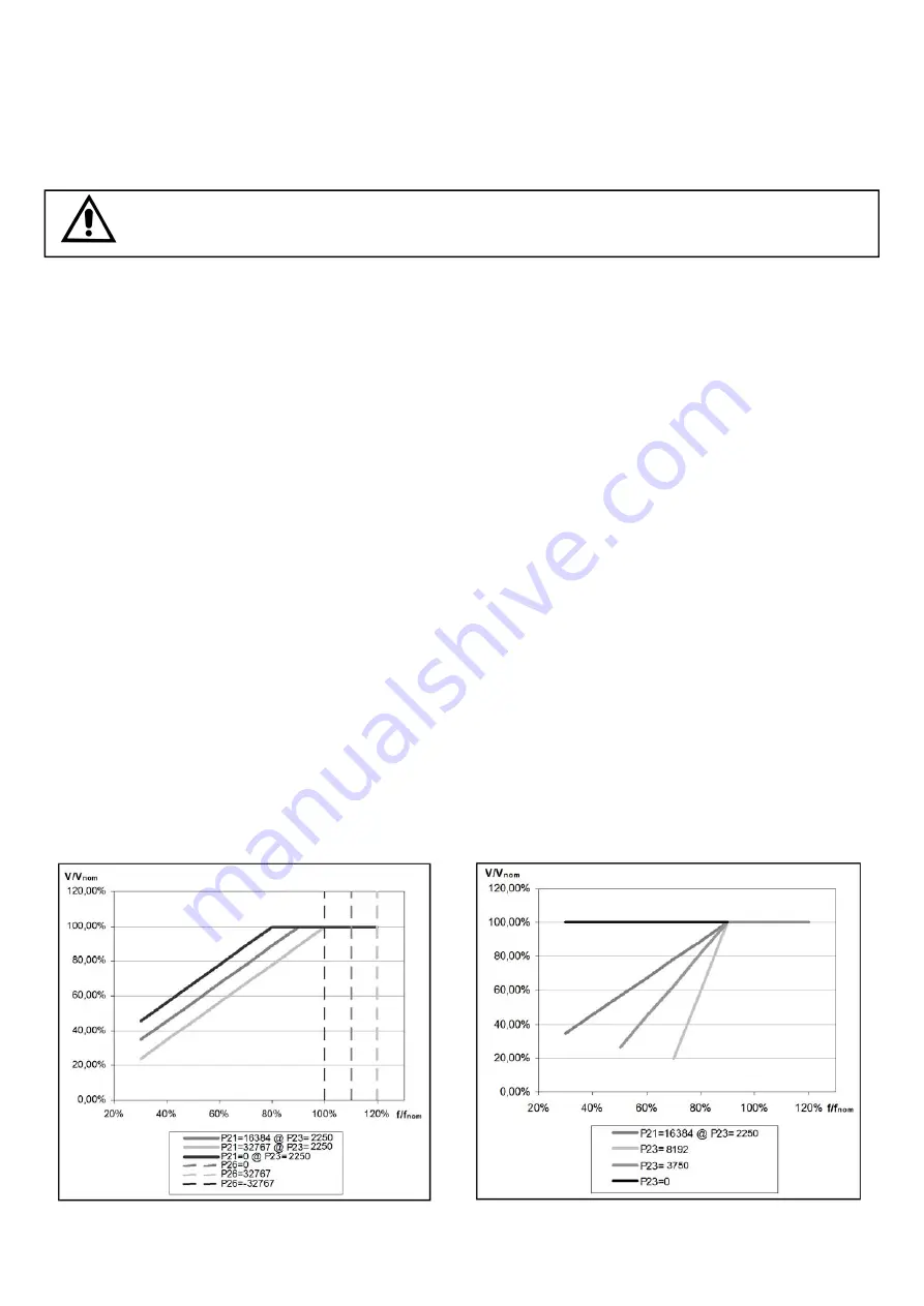
Parameter P[23]
sets the slope of the voltage/frequency curve; the default value is
1875
. An increase in the
value of P[23] involves a greater reduction of the voltage as a function of the reduction in frequency. A
decrease in the value of P[23] involves a lower reduction of the voltage until the limit of P[23]=0, which means
that there is no reduction in voltage. . The above-mentioned calibrations are simplified a lot by using the DxR
terminal software which allows, in the
Settings/UFLO&LAMS
menu, through a graphic interface, to change
parameters 21 and 23 (with a concurrent disabling of the Hz trimmer) providing the preview of the V/f ratio in
the setting phase.
WARNING:
Overheating could occur, which is dangerous for the machine, if the voltage is not
lowered enough to decrease the excitation when the alternator is functioning at a reduced speed.
4.2 Calibration with a supervision unit
Use the following procedure in order to calibrate the underspeed protection:
1) If the machine has to operate at 60 Hz, make sure the bridge, between terminals 25 and 26 is inserted, or
activate 50/60 (ref
. Settings/UFLO&LAMS
menu).
2) If the Hz trimmer is enabled, the value of the protection intervention threshold is read at location L[34],
otherwise it is entered directly at parameter P[21].
The value 26214 entered at parameter P[21] (or read at location L[34]) corresponds to an intervention
at 48/57,5 Hz (depending on whether 50/60 is activated or not).
Values between 0 and 26214 correspond to an intervention that varies from 40/48 Hz to 48/57,5Hz.
Values between 26214 and 32767 correspond to an intervention that varies from 48/57,5 Hz to 50/60Hz.
The operation is much facilitated by the use of the DxR terminal software which provides a graphic repre-
sentation of the time evolution of the measured frequency (red line) and of the intervention threshold
(green line)
3) when the speed decreases under the threshold value the voltage of the generator starts to diminish and
alarm 6 is simultaneously visualized on the LED and on the main window of the DxR Terminal software
4) By increasing speed, the generator voltage will normalise and the 6 alarm will disappear.
4.3 Calibration without a supervision unit
NOTE: This calibration can be performed only if the Hz trimmer and 50/60 jumper have been previously
enabled.
Use the following procedure in order to calibrate the under speed protection:
1) Rotate the Hz trimmer entirely in the counter clockwise direction.
2) If the machine has to operate at 60 Hz, ensure that the bridge is inserted between terminals 25 and 26
3) Bring the generator to 96% of the nominal speed.
4) Slowly turn the “Hz” trimmer, rotating it clockwise until the generator voltage begins to drop and ascertain
that the indicator light simultaneously begins flashing rapidly.
5) By increasing speed, the generator voltage will normalise and the alarm will disappear.
6) Set the speed to the nominal value
fig. 11a: Underspeed and Overspeed protection,
P[21] and P[26]
fig. 11b: Voltage slope in underspeed protection,
P[23]


