


USB-1208HS User's Guide
Functional Details
13
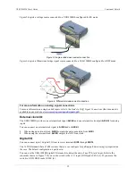
Figure 7. Schematic showing switch detection by digital channel DIO0
Pull-up/down configuration
Each of the 16 DIO bits on the USB-1208HS has a 47
kΩ pull
-up/pull-down resistor. To configure these bits for
either a +5 V pull-up or a 0 V pull-down option, open the device case to access the jumper labeled
W34
. The
pull-up/pull-down voltage is common to all of the internal 47
kΩ resistors.
Complete the following steps to set the W34 jumper:
1.
Turn over the USB-1208HS and rest it on its top on a flat, stable surface.
2.
Peel off the four rubber feet on the bottom of the module to access the screws.
3.
Remove the four screws shown in Figure 8 from the bottom of the device.
Figure 8. Location of screws connecting bottom and top sections of case
4.
Holding both the top and bottom sections of the module, turn it back over, rest it on the surface, and
carefully remove the top section of the case.
5.
Set the jumper to either pull-up or pull-down (see Figure 9 and Figure 10).
Figure 9. Location of W34 jumper (default pull-down setting shown)


