


USB-1208HS User's Guide
Functional Details
12
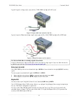
Figure 5 depicts a voltage source connected to a USB-1208HS configured for SE mode.
Figure 5. Single-ended measurement connection
Figure 6 depicts a Wheatstone bridge signal source connected to a USB-1208HS configured for DIFF mode.
Figure 6. Differential measurement connection
For more information on analog signal connections
For more information on single-ended inputs, refer to the
Guide to DAQ Signal Connections
(this document is
available on our web site atExternal clock I/O
The USB-1208HS provides one external clock input (
AICKI
) and one external clock output (
AICKO
) for analog
inputs.
You can connect an external clock signal to
AICKI
and/or
AOCKI
.
When using an external clock,
AICKO
outputs the pulse generated from
AICKI
.
When using the internal clock,
AICKO
outputs the
ADC scan clock.
Digital I/O
You can connect up to 16 digital I/O lines to screw terminals
DIO0
through
DIO15
.
The 16 DIO terminals have 47 k
Ω
resistors that you can configure for pull-up/pull-down using a jumper inside
the case. The default configuration is pull-down.
You can use the USB-1208HS digital I/O terminals to detect the state of any TTL-level input. Refer to the
schematic shown in Figure 7. If you set the switch to the +5 V input, DIO0 reads
TRUE
(1). If you move the
switch to GND, DIO0 reads
FALSE
(0).


