PCI-2515 User's Guide
Installing the PCI-2515
11
3.
To test your installation and configure your board, run the
Insta
Cal utility installed in the previous section.
Refer to the
Quick Start Guide
that came with your board for information on how to initially set up and
load
Insta
Cal.
If your board has been powered-off for more than 10 minutes, allow your computer to warm up for at least
30 minutes before acquiring data. This warm-up period is required in order for the board to achieve its rated
accuracy. The high speed components used on the board generate heat, and it takes this amount of time for a
board to reach steady state if it has been powered off for a significant amount of time.
Configuring the hardware
All hardware configuration options on the PCI-2515 are software-controlled. You can select some of the
configuration options using
Insta
Cal, such as the analog input configuration (16 single-ended or eight
differential channels), and the edge used for pacing when using an external clock. Once selected, any program
that uses the Universal Library initializes the hardware according to these selections.
Information on signal connections
General information regarding signal connection and configuration is available in the
Guide to Signal
Connections
. This document is available on our web site at
www.mccdaq.com/signals/signals.pdf
Connecting the board for I/O operations
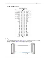
Connectors, cables – main I/O connector
Table 2-1 lists the board connectors, applicable cables, and compatible accessory products for the PCI-2515.
Table 2-1. Board connectors, cables, and compatible hardware
Connector type
68-pin standard "SCSI TYPE III" female connector
HDMI connector (targeted for future expansion)
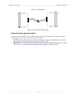
Compatible cables (for the 68-pin SCSI connector)
CA-68-3R — 68-pin ribbon cable; 3 feet.
CA-68-3S — 68-pin shielded round cable; 3 feet.
CA-68-6S — 68-pin shielded round cable; 6 feet.
Compatible accessory products
TB-100 terminal connector
RM-TB-100
Summary of Contents for PCI-2515
Page 1: ......


