


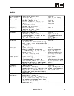


Models
Characteristic data
for all versions
(basic equipment)
Voltage supply 12V or 24V DC
output signal ±5V
limiting frequency 250Hz
optionally 2.5kHz or 10kHz;
remote controllable null balancing above
2mV/V;
input sensitivity 2mV/V,
optionally 3.5mV/V or 1mV/V
GSV-1L,
GSV-1H, GSV-1HSW,
GSV-1A
GSV-1M
GSV-1T8
GSV-1A8
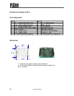
L-Version:
Printed circuit board
LxBxH 30mm x 40mm x 6,5mm;
2 gold-plated pins, 8-pole
GSV-1L
A-Version
Aluminum die-cast housing
LxBxH 64mm x 58mm x 34mm
4 amplificaiton stages (1x-2x-4x-10x) and
trimmer (1x...10x)
±5V, ±10V, 4...20mA, 0...20mA
GSV-1A
Option xV: remote
controllable amplification
switching
Option 718: plug
connection
M-Version
Cast housing, IP67
cast printed circuit board in module housing
55mm x 36mm x 17mm with miniature round
plugs type 718
±5V
GSV-1M
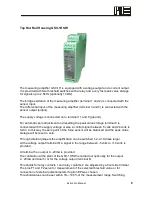
H-Version:
Top hat rail housing
BxLxH 12.5mm x 114.5mm x 99mm;
4 amplification stages (1x-2x-4x-10x) and
trimmer (1x...10x)
±5V, ±10V, 4...20mA, 0...20mA
GSV-1H
amplification switching
Option TR: stepless
amplification setting via
trimmer potentiometer
HSW-Version:
Top hat rail housing
BxLxH 25mm x 114.5mm x 99mm;
4 amplification stages (1x-2x-4x-10x)
peak value store, 2 threshold values with
relay (8A), sensor output for potentiometer
setting 0...1 Volt, output signal 0...+5V
GSV-1HSW
Option EP: external
potentiometer connectable
for adjusting the threshold
values
T-Version,
8 channels
Table top housing
BxLxH 158mm x 199 x 62mm
8 measuring channels, front side 15 pole Sub
D input socket, rear side BNC socket,
external power supply, zero-setting button,
output signal ±5V
GSV-1T8
Option AD: 37-pole Sub-D
socket for connecting with
AD insertable card
A-Version,
8 channels
Aluminum portable housing, IP65
BxLxH 169mm x 100 x 52mm
8 measuring channels, front side 4 pole
sockets type 718, rear side 9-pole Coninvers
socket, external power supply, zero-setting
button, optionally with handle
output signal ±5V
GSV-1A8
Instruction Manual
5
Summary of Contents for GSV-1
Page 3: ...Strain Gage Measuring Amplifier GSV 1 Instruction Manual 3...
Page 19: ......


