


v: resistance for determining the input sensitivity
a: short-circuit bridge for determining the supply voltage (12V
DC or 24V DC)
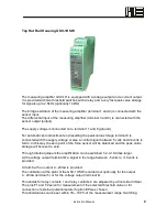
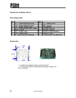
Printed Circuit Board GSV-1L
Pin Configuration
St 1
St 2
1
-U
D
: negative differential input
1
+U
B
: voltage supply
2
+U
D
: positive differential input
2
GND : ground
3
+U
S
: positive bridge supply
3
+5V stabilized
4
-U
S
: negative bridge supply (GND) 4
internally reserved
5
GND : ground
5
internally reserved
6
+U
A
: analog output
6
op8 volts stabilized
7
+U
B
: voltage supply
7
optional –7 volts
8
T: control input zero balancing
8
T: control input, zero balancing
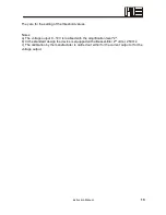
Dimensions
18
Instruction Manual
40,5
3
0
35,56
St 1
St 2
1
8
1
8
2
6
36
Ø2,5
Summary of Contents for GSV-1
Page 3: ...Strain Gage Measuring Amplifier GSV 1 Instruction Manual 3...
Page 19: ......