MDL Solutions PFWSL-01 Installation, Operation & Service Manual Download Page 9


Page 8 of 53


SK2017 AHRI PFWSL-V/P-AECM-001
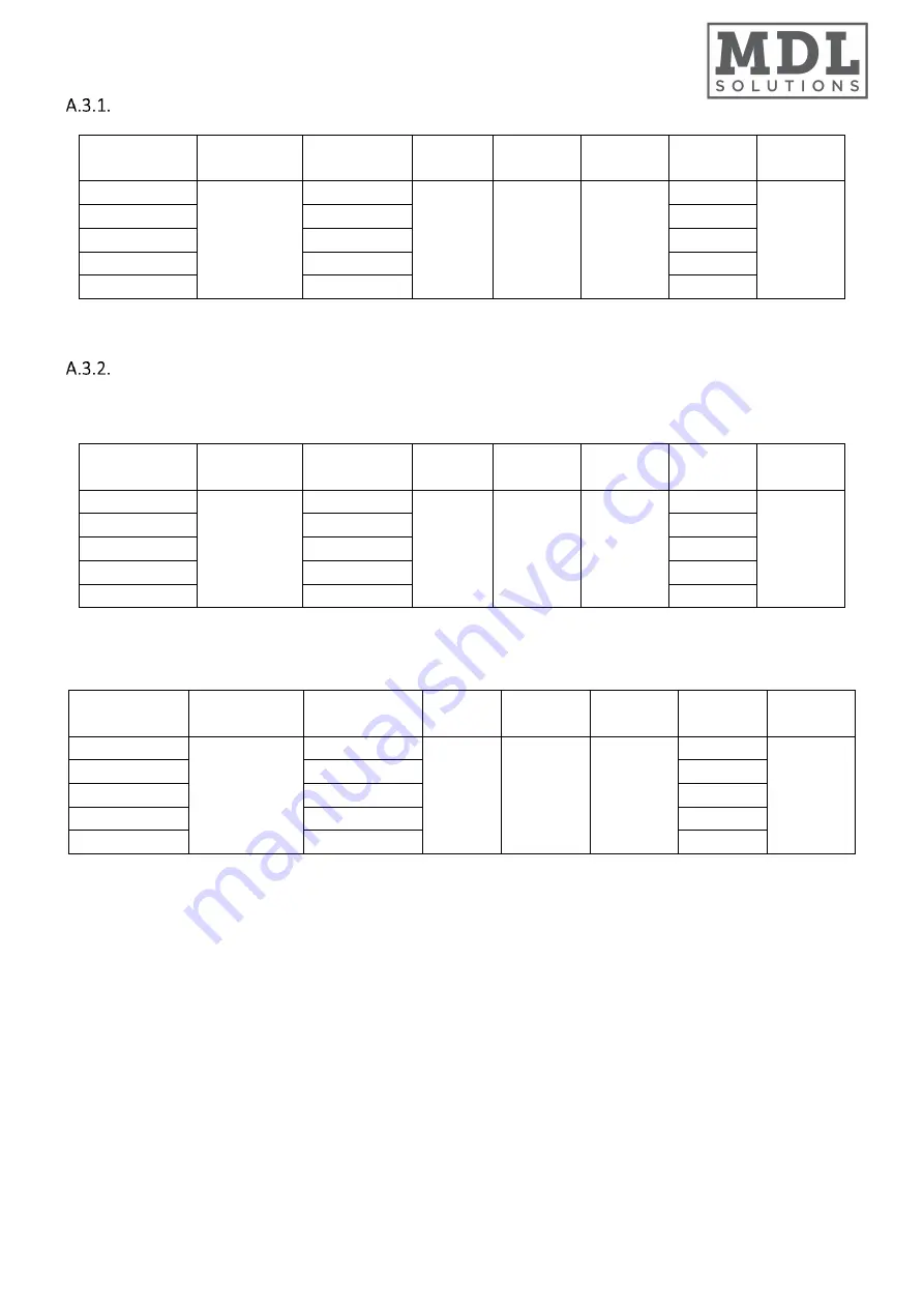
 

A.3.


Coil Data


2-Pipe Systems


Model 

Fin height 

Fin Length 

Fins per 

Inch 

No. of   

Rows 

Fin width   

No. of   

Circuits 

Tube Ø  

PFWSL-01 

11-13/16 

11-7/8 

15.0 

1-3/4 

3/8 

PFWSL-02 

19-3/4 

PFWSL-03 

27-5/8 

PFWSL-04 

35-1/2 

PFWSL-05 

43-3/8 


4-Pipe Systems


Cooling Coil 


Model 

Fin height 

Fin Length 

Fins per 

Inch 

No. of   

Rows 

Fin width 

No. of   

Circuits 

Tube Ø  

PFWSL-01 

11-9/16 

11-7/8 

16.5 

1/4 

PFWSL-02 

19-3/4 

PFWSL-03 

27-5/8 

PFWSL-04 

35-1/2 

PFWSL-05 

43-3/8 


Heating Coil 


Model 

Fin height   

Fin Length   

Fins per 

Inch 

No. of   

Rows 

Fin width 

No. of   

Circuits 

Tube Ø  

PFWSL-01 

11-9/16 

11-7/8 

16.5 

1/2 

1/4 

PFWSL-02 

19-3/4 

PFWSL-03 

27-5/8 

PFWSL-04 

35-1/2 

PFWSL-05 

43-3/8 


(All dimensions are approximate within 1/16 of an inch of those indicated.)


Summary of Contents for PFWSL-01

Page 1: ...SK2017 AHRI PFWSL V P AECM 001 ...

Page 2: ... manage every stage in the manufacturing of our products Throughout the production process we maintain strict control starting with our extensive resources in research and development through to the design and manufacture of almost every individual component from molded plastics to the assembly of units and controllers WEEE MARK Quality Controlled from Start to Finish All products conform to the W...

Page 3: ...enance 18 C 3 Filter Installation Cleaning 18 C 4 Fan Motor Assembly Maintenance 19 D Control Specifications Complete Function PCB S Type Control 20 D 1 I O Port Definitions 20 D 2 Wiring Diagrams 21 D 2 1 Standard S Type Control PCB 21 D 2 2 Master Slave Networking Wiring Diagram 22 D 3 Configuration Settings 23 D 4 Control Logics for 2 Pipe System 25 D 4 1 With Valve Configuration 25 D 4 2 Witho...

Page 4: ... PCB 42 F 4 2 Zone Control Wiring Diagram On Off Thermostat 43 F 5 Control Logics Specification 44 F 5 1 Unit Power On Off 44 F 5 2 Alarm Protection and Error Display 44 F 5 3 Modulating Signal Input 44 F 6 LED Display and Error Description 44 G User Interface 45 G 1 Remote Handset for S Type Control 45 G 2 Wired Wall Pad Controller for S Type Control 46 G 3 Thermostat for W Type Control 47 G 4 Re...

Page 5: ...board PCB with integrated group control functionality W Flexible function onboard PCB with zone control functionality P Chilled Hot Water 4 Pipe V Chilled Hot Water 2 Pipe VEH Chilled Water 2 Pipe with Electric Heater 01 05 Unit Sizes See General Specification section A for cooling and heating capacities PFWSL Super Slim Universal Unit ...

Page 6: ... which color is RAL9010 HEAT EXCHANGER The heat exchanger is a highly efficient coil in which copper pipes and aluminum fins are fixed by mechanical expansion Coil connections are provided with an anti torsion system hand air vent and water purge valves Coils are tested at the pressure of 25 bar and recommended for operating at 8 bar Blower and Motor The unit incorporates only specially designed a...

Page 7: ...Sound Sound Power Level dB A 42 35 33 44 41 35 47 43 37 47 44 38 50 46 40 Sound Pressure Level 33 26 24 35 32 26 38 34 28 38 35 29 41 37 31 Electrical Fan Motor Power H W 12 14 24 18 24 M 8 10 15 13 15 L 5 6 9 8 9 Fan Motor Running Current 115V_H A 0 11 0 127 0 218 0 164 0 218 Hydraulic Cooling Water Flow Rate H GPM 0 74 1 25 1 84 2 29 2 65 M 0 62 1 04 1 53 1 89 1 26 L 0 43 0 7 1 13 1 61 1 9 Cooli...

Page 8: ...0 46 40 Sound Pressure Level 33 26 24 35 32 26 38 34 28 38 35 29 41 37 31 Electrical Fan Motor Power H W 12 14 24 18 24 M 8 10 15 13 15 L 5 6 9 8 9 Fan Motor Running Current 115V H A 0 21 0 24 0 42 0 31 0 42 Hydraulic Cooling Water Flow Rate H GPM 0 74 1 25 1 79 2 22 2 58 M 0 62 1 03 1 49 1 84 2 08 L 0 43 0 7 1 09 1 56 1 84 Cooling Pressure Drop H Ft Hd 2 1 7 1 7 6 4 4 6 7 M 1 1 5 1 5 6 3 2 4 7 L ...

Page 9: ...ooling Coil Model Fin height Fin Length Fins per Inch No of Rows Fin width No of Circuits Tube Ø PFWSL 01 11 9 16 11 7 8 16 5 2 1 2 1 4 PFWSL 02 19 3 4 2 PFWSL 03 27 5 8 3 PFWSL 04 35 1 2 4 PFWSL 05 43 3 8 4 Heating Coil Model Fin height Fin Length Fins per Inch No of Rows Fin width No of Circuits Tube Ø PFWSL 01 11 9 16 11 7 8 16 5 1 1 2 1 1 4 PFWSL 02 19 3 4 1 PFWSL 03 27 5 8 1 PFWSL 04 35 1 2 2...

Page 10: ...4 Dimensions MODEL PFWSL 01 PFWSL 02 PFWSL 03 PFWSL 04 PFWSL 05 L 29 1 8 37 44 7 8 52 3 4 60 5 8 H 22 13 16 22 13 16 22 13 16 22 13 16 22 13 16 W 5 1 8 5 1 8 5 1 8 5 1 8 5 1 8 All dimensions are approximate within 1 16 of an inch of those indicated ...

Page 11: ...S14HFCA 23010101 D20 G3 4 2 3 16 1 7 8 7 8 2 1 2 3 Way 3 4 Valve Body Valve Code valve body ON OFF thermoelectric actuator Valve Body Dimensions mm DN A B C D SGS14HFCA 23010102 D20 G3 4 2 3 16 3 7 16 2 4 1 16 All dimensions are approximate within 1 16 of an inch of those indicated 0 2 4 6 8 10 12 14 16 0 0 5 1 1 5 2 2 5 3 3 5 P psi Cv US gpm psi Differential Pressure Chart for 3 4 valve ...

Page 12: ...moelectric actuator Valve Body Dimensions mm DN A B C D SGS14HFCA 23020101 D15 G1 2 2 1 16 1 7 8 3 4 2 1 2 All dimensions are approximate within 1 16 of an inch of those indicated 0 2 4 6 8 10 12 14 16 0 0 2 0 4 0 6 0 8 1 1 2 1 4 1 6 1 8 2 P psi Cv US gpm psi Differential Pressure Chart for 1 2 Valve ...

Page 13: ...g and servicing fan coil unit should be performed by qualified service personnel only This appliance is not intended for use by persons including children with reduced physical sensory or mental capabilities or persons lacking in experience and knowledge of the appliance unless they have been given supervision or instruction concerning it User of this appliance is responsible for his her own safet...

Page 14: ...nnection and check for leakage 5 Complete the electrical connection as shown in the wiring diagrams 6 Remount the front panel return air grille and filter FOR WALL MOUNTED WITH BOTTOM RETURN 1 Open the top left and right covers to loosen the 8 screws 2 Lift and remove the front panel 3 Keep a minimum clearance of 3 1 8 from the floor 4 Secure the mounting brackets to the wall then suspend the unit...

Page 15: ...ve the filter Step 2 Lift the front panel and remove it B 4 Electrical Connection The fan coil comes fully wired and only requires connecting to the mains electricity supply and to any room controls Remove the front panel then control box is shown below Connect the wires according to wiring diagram ...

Page 16: ...am of water connections 1 Fan 2 Heat exchanger 3 Manual bleeds 4 Joint 5 Valve CONDENSATE DRAINAGE For use in air conditioning systems the fan coils are fitted with a condensate collecting tray to which a drainpipe can be connected Connect an insulated drainage pipe inside ø 5 8 to the hole of the tray and direct it towards a suitable drain Notes i Check that the condensation flows out regularly i...

Page 17: ...izontal type Piping for 2 Pipe System Piping for 4 Pipe System 3 Way 4 Port Valve 3 4 2 Way Valve 1 2 for Cooling Coil 2 Way Valve 1 2 for Heating Coil Hot Water Outlet 1 2 Horizontal Drain Pan Chilled Water Outlet 1 2 Water Outlet 3 4 Water Inlet 3 4 Chilled Water Inlet 1 2 Hot Water Inlet 1 2 ...

Page 18: ...converted into forced drainage by attaching the condensate drain pump available as an accessory Chilled Water Outlet 1 2 Chilled Water Inlet 1 2 Hot Water Inlet 1 2 Vertical Drain Pan 2 Way Valve 1 2 for Heating Coil Hot Water Outlet 1 2 2 Way valve 1 2 for Cooling Coil Vertical Drain Pan Water Outlet 3 4 Water Inlet 3 4 3 Way 4 Port Valve 3 4 ...

Page 19: ...be brushed with a soft brush or vacuumed with a vacuum cleaner 6 If the water coil is not being used during the winter season it should be drained or an anti freezing solution should be added to the water circuit to avoid freezing C 2 Regular Maintenance 1 Inspect and clean the condensate drain pan to avoid any clogging of drainage by dirt dust etc Inspect drainage piping to ensure the proper cond...

Page 20: ... AHRI PFWSL V P AECM 001 C 4 Fan Motor Assembly Maintenance Step 1 Remove the front panel Step 2 Loosen screws on the mounting brackets EC motor can be removed Step 3 Once finished with maintenance remount the front panel ...

Page 21: ...ltage output Fan 1 CN4 Fan 1 driver and motor connection port Fan2 CN5 Fan 2 driver and motor connection port Valve1 MTV1 2 pipe coil circuit valve output chilled hot water valve Voltage output L 4 pipe coil circuit valve output chilled water valve Voltage output L Valve2 MTV2 Reserved 4 pipe coil circuit valve output hot water valve Voltage output L Water pump PUMP Power supply to condensate pump...

Page 22: ...Page 21 of 53 SK2017 AHRI PFWSL V P AECM 001 D 2 Wiring Diagrams Standard S Type Control PCB ...

Page 23: ...Page 22 of 53 SK2017 AHRI PFWSL V P AECM 001 Master Slave Networking Wiring Diagram Master Unit Slave Unit Connect to other slave units ...

Page 24: ...e only available SW8 0 SW7 1 Cooling and heating modes available SW8 1 with EH functioning as primary Master Slave setting SW6 1 Master SW6 0 Slave Preheat temperature setting SW4 1 82 4oF SW4 0 96 8oF 230VAC on off valve setting SW3 1 With valve SW3 0 Without valve 2 pipe 4 pipe system configuration SW2 1 4 pipe system SW2 0 2 pipe system PR O contact setting SW1 1 Window contact remote on off Wh...

Page 25: ...f system failure or cessation of power supply The restored parameter data set depends on the type of user interface a Handset only user interface When the power ON signal is received by the fan coil unit and no wired wall pad is installed the Mode Fan Speed Set temperature will be the same as the handset setting before the last power OFF b Wall pad only OR wall pad and handset user interface When ...

Page 26: ... d The range of Ts is 61 86ºF e Indoor fan speed can be adjusted for low medium high and auto f MTV1 will delay for 30 seconds before it is turned on g MTV1 will delay for 120 seconds before it is turned off Heat mode with electrical heater as booster a MTV2 and AUX2 are always off b If Tr Ts 1 8ºF or 7 2ºF if economy contact is activated heat operation is activated MTV1 and AUX1 are turned on Ind...

Page 27: ...ays off b If Tr 77 ºF MTV1 and AUX2 will be ON for 3 minutes and OFF for 4 minutes c If 61 ºF Tr 77 ºF MTV1 and AUX2 will be ON for 3 minutes and OFF for 6 minutes d If Tr 61 ºF MTV1 and AUX2 will be turned off for 4 minutes e At the end of the above dehumidification cycle system will decide the next dehumidification control option Indoor fan will run at low speed throughout the dehumidification p...

Page 28: ...TV2 and AUX2 are always off b If Tr Ts 1 8 ºF or 7 2 ºF if economy contact is activated heat operation is activated AUX1 is turned on Indoor fan runs at the set speed c If Tr Ts heat operation is terminated AUX1 is turned off Indoor fan runs at 200 rpm d If Ti1 104 ºF the electrical heater is turned on If 104 Ti1 113 ºF the electrical heater is kept original state If Ti1 113 ºF the electrical heat...

Page 29: ... economy contact is activated heat operation is activated MTV2 and AUX1 are turned on Indoor fan runs at the set speed c If Tr Ts heat operation is terminated MTV2 and AUX1 are turned off Indoor fan runs at 200rpm d The range of Ts is 61 86 ºF e Indoor fan speed can be adjusted for low medium high and auto f MTV2 will delay for 30 seconds before it is turned on g MTV2 will delay for 120 seconds be...

Page 30: ...and the unit will work as the Pre heat and Post heat set times DEHUMIDIFICATION MODE a MTV2 AUX1 and heater always off b If Tr 77 ºF MTV1 and AUX2 will be ON for 3 minutes and OFF for 4 minutes c If 61 ºF Tr 77 ºF MTV1 and AUX2 will be ON for 3 minutes and OFF for 6 minutes d If Tr 61 ºF MTV1 and AUX2 will be turned off for 4 minutes e At the end of the above dehumidification cycle system will dec...

Page 31: ...annot change until it has run for more than 30 seconds Fan speed is regulated according to the profile below Fan speed cannot change until it has run for more than 30 seconds Fan speed is regulated according to the profile below After 30 seconds the fan speed is modulated according to the difference between the room temperature and the set temperature The controller adjusts the motor signal input ...

Page 32: ...tch On The Front Panel a This is a TACT switch to select Cool Heat Off operation mode b In COOL mode the set temperature of the system is 75 ºF with auto fan speed There are no timer and sleep modes c In HEAT mode the set temperature of the system is 75 ºF with auto fan speed There are no timer and sleep modes d Master unit that does not use a wall pad will globally broadcast D 12 Electric Heater ...

Page 33: ...turn air sensor failure Green LED blinks 3 times stops for 3s Room sensor unplugged or damaged 1 Check if Tr plug is connected or not 2 Check if sensor s resistance is correct or not Indoor coil sensor 1 failure Green LED blinks 4 times stops for 3s Ti1 sensor unplugged or damaged 1 Check if Ti1 plug is connected or not 2 Check if sensor s resistance is correct or not Indoor coil low temperature p...

Page 34: ...times stops for 3s Check unit 15 communication plug and fix it Unit 16 failure RED LED blinks 16 times stops for 3s Check unit 16 communication plug and fix it Unit 17 failure RED LED blinks 17 times stops for 3s Check unit 17 communication plug and fix it Unit 18 failure RED LED blinks 18 times stops for 3s Check unit 18 communication plug and fix it Unit 19 failure RED LED blinks 19 times stops ...

Page 35: ...ote Control Handset to Set Master Control Unit 1 Connect all the units PCBs according to the wire color and type of connector 2 Select the master unit by setting DIPA S1 SW6 to ON 1 in the PCB 3 Ensure the DIPA S1 SW6 is set to OFF 0 in the PCB on each slave unit 4 Switch on the units by connecting the main power supply 5 Using the handset set the operation parameters for the master unit which wil...

Page 36: ...ox 2 Communication plug A B A B is printed on the main PCB When you connect the wires please ensure connection of A to A and B to B 3 Connection wire i If the total length of wire is more than 1000m please use shielded wire in order to protect the signal transmission ii Complete wire connection First unit Middle unit Last unit ...

Page 37: ...e wire contact by using a multimeter c Check 1 and 2 3 and 4 5 and 6 to be sure the connections are correct d If the resistance between two wire contacts is too high please check and reconnect the wire contacts 4 Reconnect the communication plug to the control box First unit Middle unit Last unit 1st contact 2nd contact 3rd contact 4th contact 5th contact 6th contact ...

Page 38: ...A S1 SW5 DIPA S1 SW4 DIPA S1 SW3 DIPA S1 SW2 DIPA S1 SW1 Unit No Remark 1 0 0 0 0 0 01 Master 0 0 0 0 0 1 02 Slave 0 0 0 0 1 0 03 Slave 0 0 0 0 1 1 04 Slave 0 0 0 1 0 0 05 Slave 0 0 0 1 0 1 06 Slave 0 0 0 1 1 0 07 Slave 0 0 0 1 1 1 08 Slave 0 0 1 0 0 0 09 Slave 0 0 1 0 0 1 10 Slave 0 0 1 0 1 0 11 Slave 0 0 1 0 1 1 12 Slave 0 0 1 1 0 0 13 Slave 0 0 1 1 0 1 14 Slave 0 0 1 1 1 0 15 Slave 0 0 1 1 1 1 ...

Page 39: ...h are used to test unit Valid Error code table Error code Description Definition 01 01H Invalid commands Received commands beyond valid commands 02 02H Invalid data address Data addresses beyond valid data address 03 03H Invalid data Data beyond definition range 04 04H Write data not successful Write data did not succeed Coils table Description Address Type Remark Unit ON OFF 100000 R W Sleep mode...

Page 40: ...07 W Calibration wired wall pad and set timer function Minute 300008 W Calibration wired wall pad and set timer function Second 300009 W Calibration wired wall pad and set timer function Hours in Timer on 300010 R W Timer ON Minute in Timer on 300011 R W Timer ON Hours in Timer off 300012 R W Timer OFF Minute in Timer off 300013 R W Timer OFF Icon of Timer ON or OFF 300014 R W BIT0 Icon of Timer O...

Page 41: ...t6 Reserved Bit7 Electrical heater failure Bit8 Motor1 Error Bit9 Motor2 Error Bit10 System parameters error Bit11 Reserved Bit12 Reserved Bit13 Reserved Bit14 Reserved Bit15 Reserved Fan speed status 400006 R Low 04 H Medium 02 H High 01 H Mode status 400007 R Cooling mode 01 H Dehumidify mode 02 H Fan mode 04 H Heating 08 H Setting temperature status 400008 R Testing only Room temperature in wal...

Page 42: ...gth 5 m Neutral N1 N2 Earth GND Signal Input Modulating signal Low voltage modulating signal input standard 0 5VDC optional 0 10VDC Digital input Programming interface TTL Low voltage digital signal input for board programming Float switch Float N A Voltage output Water pump PUMP N A EC motor CN4 5 wire connection with 230VAC power supply to EC motor and 0 5VDC modulating signal output Stepping mo...

Page 43: ...Page 42 of 53 SK2017 AHRI PFWSL V P AECM 001 F 4 Wiring Diagrams Standard W Type Control PCB ...

Page 44: ...BL BL BL M BL RELAY RELAY BLDC EC MOTOR HV Gnd Vcc Vsp FG FLOAT float control switch for pump RELAY CPU SM1 SM2 CN2 AI1 NC CN4 X DIS TTL L M H AUTO N 0 5VDC 0 10VDC S3 closed BK YL BR OR Auto speed signal 230V 50HZ CN1 ALARM GY RD GR S1 L1 N1 N2 PUMP BL RD WH BR OR BK BL YL GR RD RD OR BR YL BL BL BK BL BL BL M BL RELAY RELAY BLDC EC MOTOR HV Gnd Vcc Vsp FG FLOAT float control switch for pump RELA...

Page 45: ...g signal To set the PCB to the optional configuration the S1 jumper must be closed F 6 LED Display and Error Description LED receiver in ABS housing with 0 5m SGS14HFCA 01010101 or 1 8m SGS14HFCA 01010102 pre wiring Flexible Function PCB W Control Type Fan speed setting LED Display Condition High speed Red LED On Normal Medium speed Yellow LED On Normal Low speed Green LED On Normal For all units ...

Page 46: ... its settings are automatically sent to the slave units Auto Cool Heat operation will be applicable in 4 pipe system only Swing and Louver functions are not applicable European version only uses degree C setting Swing It is not available Interchange o F and o C on Display Press up and down buttons for 3 seconds then release Louver It is not available ...

Page 47: ...be set by dip switch 1 setting When dip switch1 is ON the temperature cannot be set In the cooling mode the setting temperature is 24 C and in heating mode the setting temperature is 21 C When dip switch is off factory setting the temperature can be set from 16 30 C A dry contact to tuned on or off the unit Room temperature and setting temperature display can be selected by dip switch 2 When dip s...

Page 48: ... the difference between room temperature and set point exceed 1 Auto MED speed When exceed 2 Auto HI speed When exceed 3 Control Motorized Valve under 2 pipe configuration If the difference between room temperature and set point exceed 1 FCU valve will be open if room temperature and set point are equal type DA will close the FCU valve with the fan still running type DB will close the FCU valve an...

Page 49: ...ernal sensor mode If external sensor is not connected it will function on the internal sensor 3 the icon will be showed 01 32 01 Communication address Parameter B When thermostat is closed press button and hold for 10 seconds 1 The thermostat will display 02 or 04 use or key to adjust 2 Press to enter next parameter setting Press or key to adjust 3 Repeat the second step above to set other paramet...

Page 50: ...1 91 85 60 8 14 69 15 05 15 41 1 4 79 8 83 17 86 64 62 6 14 03 14 37 14 7 3 2 75 39 78 53 81 76 64 4 13 41 13 72 14 03 5 71 26 74 18 77 19 66 2 12 81 13 1 13 4 6 8 67 37 70 1 72 9 68 12 24 12 52 12 79 8 6 63 73 66 26 68 88 69 8 11 7 11 96 12 22 10 4 60 3 62 67 65 1 71 6 11 19 11 43 11 67 12 2 57 08 59 28 61 55 73 4 10 71 10 93 11 15 14 54 05 56 1 58 22 75 2 10 24 10 45 10 66 15 8 51 19 53 12 55 08...

Page 51: ... 0 9697 1 012 125 6 3 225 3 326 3 43 192 2 0 8998 0 9401 0 9818 127 4 3 105 3 204 3 305 194 0 8721 0 9115 0 9522 129 2 2 99 3 086 3 185 195 8 0 8455 0 8839 0 9237 131 2 88 2 974 3 07 197 6 0 8198 0 8573 0 8961 132 8 2 774 2 866 2 959 199 4 0 795 0 8316 0 8696 134 6 2 673 2 762 2 854 201 2 0 7711 0 8069 0 8439 136 4 2 576 2 663 2 752 203 0 748 0 783 0 8192 138 2 2 483 2 568 2 655 204 8 0 7258 0 759...

Page 52: ...voltage Check fuse on board Place in the ON position Check the room control Check fan motor Filter clogged Air flow obstructed Room control regulation Incorrect water temperature Air present Insufficient output Clean the filter Remove obstacles Check the room air sensor Check the water source Check the air vent Contact between metal parts Loose screws Noise and vibrations Check for loosening parts...

Page 53: ...eater Electric Heater module is supplied for winter heating as an alternative to the auxiliary hot water coil Electric Heater is installed in the same way and same position as the Auxiliary 1 row heating coil for 4 pipe system Note Airflow should not drop below the values for minimum speed ...

Page 54: ...teel drain pan for suspended ceiling installation or built in horizontal installation with left sided coil connections DPANPS UNSL RHLH is a painted steel drain pan for floor standing installation fixed wall installation and built in vertical installations Suitable for left side and right side unit coil connections DPANPS UNSL RHLH DPANPS UNSL RH DPANPS UNSL LH J 3 ABS Supporting Feet ABSFT UNISL ...

Page 55: ...Page 72 of 72 SK2016 PFWBC V P ECM 001 MDL Solutions 2275 Upper Middle Rd E Oakville ON L6H0C3 general mdlsoln com 289 799 3414 www mdlsoln com ...

Reviews: