background image

McQuay IM 777-1

3

Installation Guidelines

Curb Mounting and Unit Leveling

Do not place a Skyline unit over an open curb unless it is 
equipped with a curb-ready base. Installation instructions for 
mounting units on a roof curb are provided in IM 770. For a 
copy, contact your local McQuay representative or visit 
www.mcquay.com. Make provisions under the unit to divert 
any moisture from entering the building below. 

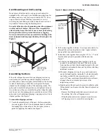
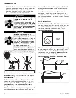
For units without roof curb mounting, place the equipment 
on a flat and level surface. Where surface irregularities 
exist, shim the base of the unit at one or more points along 
the length of the rails to prevent distortion or sagging. 
Uneven or distorted sections cause misfit or binding of the 
doors and panels and improper draining of drain pans. See 
Figure 4

.

Figure 4: Leveling the unit

Assembling Sections

If the unit is shipped in more than one shipping section, rig 
each section into position separately. Shipping sections are 
provided with a connection splice joint attached on the leaving 
air side of the shipping section that seals against the frame 
channel on the entering-air side of the adjoining section. The 
splice joint is insulated and provides an air-tight seal between 
two sections once they are assembled together. Align the splice 
joint to seat into the mating gasket to provide an air seal. If the 
splice joint was bent during shipping or rigging, restore it to its 
original position. See Figure 7

.

To assemble shipping sections:

1

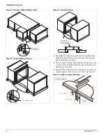
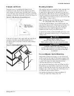
Caulk all assembly joints of the unit—Before joining the 
sections, apply at least 1/4 inch diameter bead of sealant to 
the mating faces of the cabinet. Use the splice joint as a 
guide for applying the sealant. See Figure 5

.

Figure 5: Apply sealant to mating faces

2

Pull sections together to fasten. Use straps and a ratchet to 
help pull the sections together securely. Apply sealant to 
any gaps that may admit moisture. 

3

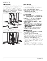
Fasten base rails together first using the 3/8"-16 × 5" bolts 
located in the splice kit provided with the unit. See 
Figure 7.

a

To fasten two shipping sections together, 4 bolts are 
needed (2 on each side of the unit). The bolts are run 
from one base rail into the other and fastened with a nut. 
Complete each section bottom and top before attaching 
additional sections.

b

If desired, shipping sections for non curb-ready units 
can be fastened together internally. To fasten internally, 
run field-provided #10 sheet metal screws or drill 
screws (4" long, maximum) through the interior frame 
channel of one unit into the splice joint of the 
neighboring section.

c

Handle units with curb-ready bases and vestibules so the 
lifting bracket can be removed after the unit is placed on 
the curbing. 

– Remove the lifting bracket that projects inward over 

the curbing. Save the self tapping screws. 

– When the adjacent section is placed in position, use 

self tapping screw to secure the bases together.

S h i m   t o   p r e v e n t  

d i s t o r t i o n   i f   w i d t h  

i s   o v e r   1 0 8 "

S h i m   s e c t i o n s   u n t i l  

t h e y   a r e   s t r a i g h t

a n d   l e v e l

1 / 4 "   d i a m e t e r

b e a d   c e n t e r e d  

i n   f a c e   o f

c l e a r a n c e

U s e   S p l i c e  

J o i n t   a s   a  

g u i d e

Summary of Contents for Skyline IM 777-1

Page 1: ...McQuay IM 782 1 1 Installation and Maintenance Manual IM 777 1 Group Applied Air Part Number IM 777 Date June 2005 2005 McQuay International Skyline Air Handler Sizes 003 090...

Page 2: ...ater Cooling Coils 8 Direct Expansion Coils 8 Steam Coils see Figure 18 on page 10 9 Water Heating Coils 11 Drain Pan Traps 11 Internal Isolation Assembly Adjustment 12 Electrical Installation 13 Oper...

Page 3: ...fore unit installation to verify this has not happened 4 Screws bolts etc for assembling sections are supplied in a bag attached to each section All necessary gasketing is applied in the factory for s...

Page 4: ...igure 2 Figure 1 Servicing space requirements Figure 2 Service clearance for electrical power devices Rigging Skyline air handlers ship as separate sections completely assembled or in modules of assem...

Page 5: ...all assembly joints of the unit Before joining the sections apply at least 1 4 inch diameter bead of sealant to the mating faces of the cabinet Use the splice joint as a guide for applying the sealan...

Page 6: ...slip the splice cap over the top panel flanges Bend the ends of the splice cap down to secure in place 6 Assemble the small splice plate at the top rail to secure the sections together at the top Use...

Page 7: ...the jam nuts Figure 10 Opening fan section door Injected Foam Insulated Panels Skyline air handlers now are furnished with double wall injected foam insulated panels Foam panels are stronger more rig...

Page 8: ...ctions are necessary See Figure 12 Figure 12 Discharge plenum If the unit has a top mixing box or economizer damper or a top duct connection field fabricate and install flashing to divert moisture fro...

Page 9: ...same actuator if the dampers are the same size If the dampers are different sizes they must be driven by separate actuators and controlled appropriately Exhaust dampers are always driven by a separate...

Page 10: ...e coils to freezing temperatures Water supply water return drain and vent connections extend through the end panel of the coil section All connections are labeled on the end panel Water supply and wat...

Page 11: ...Use thermostatic traps only for air venting Use bucket traps for on off control only Locate traps at least 12 inches below the coil return connection Multiple coil installation Individually trap each...

Page 12: ...aker 1 2 check valve Steam main Return main 12 min Vacuum breaker 1 2 check valve Steam main Return main 12 min Full size of return conn Check Valve Strainer Gate Valve Control valve modulating two po...

Page 13: ...n pan trap to allow condensate to drain freely On both blow through and draw through units the trap depth and the distance between the trap outlet and the drain pan outlet must be twice the static pre...

Page 14: ...he cap screw when adjustments are completed For models 040 through 090 the isolators should be at equal height during fan operation 6 Center the fan outlet in the outlet panel opening If adjustment is...

Page 15: ...m of the fan motor junction box See Figure 22 Figure 22 Electrical conduit location CAUTION The base section of each cabinet has a drip pan installed below every panel that drains to the outside frame...

Page 16: ...t m me la mort L alimentation lectrique du moteur du ventilateur de m me que la mise la terre du ch ssis du moteur doivent tre faits conform ment aux codes d nstallations lectriques en vigueur WARNING...

Page 17: ...wheel s axially as needed and retightening setscrews 3 To obtain dimension B loosen screw and washer fasteners around periphery of funnel s shifting funnel radially as required and re torquing fastene...

Page 18: ...5 440 24 5 500 27 560 30 620 33 750 36 5 810 40 25 880 44 5 940 49 1 000 54 25 1 060 60 1 120 Overlap Table 5 Wheel to inlet funnel relationship inline fans Wheel funnel overlap Size Overlap 150 375 1...

Page 19: ...1 56 24 00 Maximum rpm Class I 3000 3000 2300 2000 1700 1500 Maximum rpm Class Il 4335 3918 3457 2858 2427 2255 300 250 200 150 100 90 80 Torque in lb 350 400 450 500 600 650 700 750 800 850 1000 1500...

Page 20: ...00 AF30 00 500 600 700 800 2000 1000 1500 1500 2000 3000 2500 Torque in lb Table 9 Operating limits plenum fans Fan operating limits Plenum fans Diameter 13 5 15 16 5 18 25 20 22 25 24 5 27 30 33 36...

Page 21: ...ble pitch sheaves Axial and radial runout of flanges uneven groove spacing out of balance Also similar faults in driven sheave b Bad V belts lumpy or mismatched belt tension too tight or too loose 4 B...

Page 22: ...the air balance replace the variable pitched motor sheave with a properly sized fixed sheave A matching fixed sheave provides longer belt and bearing life and minimizes vibration Initially it is best...

Page 23: ...number of turns from closed position 7 Verify that all keys are in place and that all se screws are tight before starting drive Check setscrews and belt tension after 24 hours service Figure 32 VP typ...

Page 24: ...t on page 24 9 Before starting the drive ensure that all keys are in place and all setscrews and all capscrews are tight Check and retighten all screws and retension belts after approximately 24 hours...

Page 25: ...hs L less than dia Seating torque Seating torque Seating torque Seating torque Length L Seating torque in lbs in lbs in lbs in lbs in lbs in lbs in lbs 1 4 20NC 150 12 5 100 87 7 3 3 16 50 5 16 11NC 3...

Page 26: ...oving belt and fan can cause severe personal injury or death During installation and filter maintenance Verify that the belt and fan guards on plenum fan units are always in place Lock and tag out fan...

Page 27: ...Filter gauge Table 15 Belt deflection force per Browning specifications Cross section Sheave diameter in Deflection force lbs Smallest sheave diameter range rpm range Cross section A B 5V Cross secti...

Page 28: ...reezing of coils Removing and Replacing Components See Access Doors and Panels on page 5 for instructions on removing panels and opening fan access doors to remove or replace components Removing the F...

Page 29: ...s See Figure 39 5 If this is an additional coil being installed and not a replacement locate the coil supply and return connections dimensionally Carefully drill holes in the end panels of the unit 6...

Page 30: ...and remove the brass plugs for the vents and drains located in the connections 2 To access bolts holding the coils in place remove the panels on both the connection and opposite connection end of the...

Page 31: ...must be prepaid The return of the part does not constitute an order for replacement Therefore a purchase order must be entered through the nearest McQuay representative The order should include part...

Page 32: ...30 McQuay IM 777 1...

Page 33: ...McQuay IM 777 1 31...

Page 34: ...32 McQuay IM 777 1...

Page 35: ......

Page 36: ...ipment its care should be a high priority For training information on all McQuay HVAC products please visit us at www mcquay com and click on training or call 540 248 9646 and ask for the Training Dep...

Reviews: