KOMAC00607-09EN
21
Unit Functions
Calculations
LWT Slope
LWT slope is calculated such that the slope represents the change in LWT over a time frame
of one minute with at least five samples per minute.
Pulldown Rate
The slope value calculated above will be a negative value as the water temperature is
dropping. For use in some control functions, the negative slope is converted to a positive
value by multiplying by –1.
Unit Enable
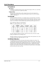
Enabling and disabling the chiller is accomplished using set points and inputs to the chiller.
The unit switch, remote switch input, and Unit Enable Set Point all are required to be on for
the unit to be enabled when the control source is set to local. The same is true if the control
source is set to network, with the additional requirement that the BAS request must be on.
Unit is enabled according to the following table.
NOTE
: An x indicates that the value is ignored.
Unit
Switch
Control
Source Set
Point
Remote
Switch Input
Unit Enable
Set Point
BAS
Request
Unit
Enable
Off x x
x x
Off
x x x Off x
Off
x x Off x x
Off
On Local On
On
x On
x Network x
x
Off Off
On Network On
On
On On
All of the methods for disabling the chiller, discussed in this section, will cause a normal
shutdown (pumpdown) of any running circuits.
When the controller is powered up, the Unit Enable Set Point will be initialized to ‘off’ if the
Unit Status After Power Failure Set Point is set to ‘off’.
Unit Mode Selection
The operating mode of the unit is determined by setpoints and inputs to the chiller. The
Available Modes Set Point determines what modes of operation can be used. This setpoint
also determines whether the unit is configured for glycol use. The Control Source Set Point
determines where a command to change modes will come from. A digital input switches
between cool mode and ice mode if they are available and the control source is set to local.
The BAS mode request switches between cool mode and ice mode if they are both available
and the control source is set to network.
Summary of Contents for AWS
Page 8: ...8 KOMAC00607 09EN Figure 5 Piping Schematic with Economizer Circuit One Circuit ...
Page 12: ...12 KOMAC00607 09EN ...
Page 54: ...54 KOMAC00607 09EN ...
Page 67: ......


