background image

KOMAC00607-09EN  

13


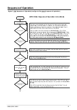
Figure 8, Circuit Sequence of Operation 

Is circuit commanded to 

start?

Is circuit commanded to 

shut down?

Pumpdown circuit

Yes

Yes

No

Unit power up

Circuit is in Off state

No

Run circuit

When the circuit begins to run, the compressor will be started and the EXV, fans, 
and other devices will be controlled as needed.  The normal circuit status at this 
time will be 

Run

.

When the circuit is commanded to shut down, a normal shut down of the circuit will 
be performed.  The circuit status during this time will be 

Run:Pumpdown

.  After 

the shut down is completed, the circuit status will normally be 

Off:Cycle Timer 

initially

.

When the circuit is in the Off state the EXV is closed, compressor is off, and all fans 
are off.    

Is circuit is enabled to 

start?

Yes

No

The circuit must be enabled before it can run.  It may be disabled for several 
reasons.  When the circuit switch is off, the status will be 

Off:Circuit Switch

.

If the BAS has disabled the circuit, the status will be 

Off:BAS Disable

.  If the circuit 

has an active stop alarm then the status will be 

Off:Cir Alarm

.  If the circuit has 

been disabled via the circuit mode set point, the status will be 

Off:Cir Mode 

Disable

.

Is compressor oil sump 

ready?

Yes

No

If the compressor is not ready due to refrigerant in the oil, the circuit cannot start.  
The circuit status will be 

Off:Refr In Oil.

Circuit is ready to start

If the compressor is ready to start when needed, the circuit status will be 

Off:Ready

.

Are compressor cycle 

timers active?

No

Yes

A minimum time must pass between the previous start and stop of a compressor 
and the next start.  If this time has not passed, a cycle timer will be active and the 
circuit status will be 

Off:Cycle Timer

.

AWS Sequence of Operation - Circuits


Summary of Contents for AWS

Page 1: ...Operating Manual KOMAC00607 09EN Date July 2009 Supercedes None Control Panel Air Cooled Screw Chillers AWS 50 Hertz R 134a ...

Page 2: ...32 COMPRESSOR CONTROL 32 CONDENSER FAN CONTROL 34 EXV CONTROL 35 ECONOMIZER CONTROL 36 LIQUID INJECTION 36 ALARMS AND EVENTS 37 SIGNALING ALARMS 37 CLEARING ALARMS 37 DESCRIPTION OF ALARMS 37 UNIT EVENTS 39 CIRCUIT STOP ALARMS 40 CIRCUIT EVENTS 44 ALARM LOGGING 45 USING THE CONTROLLER 46 NAVIGATING 47 OPTIONAL REMOTE USER INTERFACE 53 START UP AND SHUTDOWN 55 TEMPORARY SHUTDOWN 55 EXTENDED SEASONA...

Page 3: ...sonal injury or equipment damage This equipment must be properly grounded Connections to and service of the MicroTech III control panel must be performed only by personnel who are knowledgeable in the operation of this equipment CAUTION Static sensitive components A static discharge while handling electronic circuit boards can cause damage to the components Discharge any static electrical charge b...

Page 4: ...owest run hours when the unit is enabled to run not necessarily running on a call for cooling and when the water temperature reaches a point of freeze possibility Two levels of security protection against unauthorized changing of setpoints and other control parameters Warning and fault diagnostics to inform operators of warning and fault conditions in plain language All events and alarms are time ...

Page 5: ...trols the MicroTech III control system will take corrective action if the chiller is operating outside of its normal design conditions If a fault condition develops the controller will shut a compressor or the entire unit down and activate an alarm output The system is password protected and only allows access by authorized personnel Except that some basic information is viewable and alarms can be...

Page 6: ...6 KOMAC00607 09EN Power Panel Layout The power panel is at the front of the unit behind the two doors to the right Figure 2 Power Panel Left Side Figure 3 Power Panel Right Side ...

Page 7: ...m liquid from the condenser is feed into the economizer where it is cooled by flashing off liquid also from the condenser The flash gas is piped to a compressor interstage point Lowering the liquid refrigerant temperature to the evaporator decreases its enthalpy heat content and results in a greater amount of heat absorption from the chilled water Brazed plate Heat Exchanger Gas to Comp Interstage...

Page 8: ...8 KOMAC00607 09EN Figure 5 Piping Schematic with Economizer Circuit One Circuit ...

Page 9: ...One of the optional BAS communication modules may be included An optional Remote Operator Interface panel may be included connected with up to nine AWS units The Advanced MicroTech III controllers used on AWS chillers are not interchangeable with previous MicroTech II controllers Figure 6 hardware structure Communication Cards BACnet IP BACnet MSTP MODbus LON Remote Operator Interface MicroTech II...

Page 10: ...as selected Figure 6 System Architecture I O Extension Compressor 1 I O Extension Compressor 2 I O Extension Compressor 3 I O Extension Compressor 4 I O Extension EXV 1 I O Extension EXV 2 I O Extension EXV 3 I O Extension EXV 4 I O Extension Fans Circuit 1 and 2 I O Extension Fans Circuit 3 I O Extension Fans Circuit 4 I O Extension Fans Circuit 3 and 4 I O Extension Alarm Limiting BAS Interface ...

Page 11: ...iller Enable set point the unit status will be Off Keypad Disable If the chiller is enabled then the unit will be in the Auto state and the evaporator water pump output will be activated After establishing flow the chiller will wait some time to allow the chilled water loop to recirculate for an accurate reading of the leaving water temperature The unit status during this time is Auto Evap Recirc ...

Page 12: ...12 KOMAC00607 09EN ...

Page 13: ... The circuit must be enabled before it can run It may be disabled for several reasons When the circuit switch is off the status will be Off Circuit Switch If the BAS has disabled the circuit the status will be Off BAS Disable If the circuit has an active stop alarm then the status will be Off Cir Alarm If the circuit has been disabled via the circuit mode set point the status will be Off Cir Mode ...

Page 14: ...olution X6 Fan VFD 2 0 10VDC 0 to 100 1000 steps resolution X7 Fan VFD 3 0 10VDC 0 to 100 1000 steps resolution X8 Fan VFD 4 0 10VDC 0 to 100 1000 steps resolution Digital Inputs Description Signal Off Signal On DI1 Unit PVM Fault No Fault DI2 Evaporator Flow Switch No Flow Flow DI3 Double Set Point Mode Switch Cool mode Ice mode DI4 Remote Switch Remote off Remote on DI5 Unit Switch Unit off Unit...

Page 15: ...rt Compressor Compressor Off Compressor On DO2 Economizer Solenoid Closed Solenoid Open DO3 Non modulating Slide Load Solenoid Closed Solenoid Open DO4 Liquid Injection Solenoid Closed Solenoid Open DO5 Modulating Slide Load Solenoid Closed Solenoid Open DO6 Modulating Slide Unload Solenoid Closed Solenoid Open X5 Spare X8 Spare I O EXV Circuit 1 to 3 Analog Inputs Description Signal Source Expect...

Page 16: ...Step 6 Fan Off Fan On Extension I O Unit Alarm Limiting POL Analog Inputs Description Signal Source Range X3 Demand Limit 4 20 mA 1 to 23 mA X4 Unit Current 4 20 mA 1 to 23 mA Analog Outputs Description Output Signal Range Not Needed Digital Inputs Description Signal Off Signal On X1 External Alarm Event External Device Failure External Device OK X2 Current Limit Enable No Limiting Limiting X5 Cir...

Page 17: ...tup Delta T 5 F 2 7 C 0 to 10 F 0 to 5 C Shut Down Delta T 2 7 F 1 5 C 0 to 3 F 0 to 1 7 C Stage Up Delta T between compressors 2 F 1 C 0 to 3 F 0 to 1 7 C Stage Down Delta T between compressors 1 F 0 5 C 0 to 3 F 0 to 1 7 C Max Pulldown 3 F min 1 7 C min 0 5 5 0 F min 0 3 to 2 7 C min Evap Recirc Timer 30 0 to 300 seconds Evap Control 1 Only 1 Only 2 Only Auto 1 Primary 2 Primary LWT Reset Type N...

Page 18: ... timer 5 min 3 20 minutes Pumpdown Pressure 14 3 PSI 100 kPa 10 to 40 PSI 70 to 280 kPa Pumpdown Time Limit 120 sec 0 to 180 sec Light Load Stg Dn Point 50 20 to 50 Load Stg Up Point 50 50 to 100 Stage Up Delay 5 min 0 to 60 min Stage Down Delay 3 min 3 to 30 min Stage Delay Clear No No Yes Max Comps Running 4 1 4 Sequence Cir 1 1 1 4 Sequence Cir 2 1 1 4 Sequence Cir 3 1 1 4 Number of Pulses 10 t...

Page 19: ... 14 5 PSI 100 to 100 kPa S Cond pressure offset 0PSI 0kPa 14 5 to 14 5 PSI 100 to 100 kPa S Oil pressure offset 0PSI 0kPa 14 5 to 14 5 PSI 100 to 100 kPa S Suction temp offset 0 F 0 C 5 0 to 5 0 deg S Discharge temp offset 0 F 0 C 5 0 to 5 0 deg S Fans Fan VFD enable On Off On M Number of fans 5 5 to 12 M Saturated Condenser Temp Target Min 90 F 32 C 80 0 110 0 o F 26 0 to 43 0 C M Saturated Conde...

Page 20: ...rcuit 10 to 60o F 23 to 15 C Dynamic Default Values The fan staging dead bands have different default values based on the VFD enable setpoint When the VFD enable setpoint is changed a set of default values for the fan staging dead bands is loaded as follows VFD is Enabled VFD is Disabled Setpoint Default loaded o F Setpoint Default loaded o F Stage 1 On Deadband 8 Stage 2 On Deadband 5 Stage 2 On ...

Page 21: ...ed Unit Switch Control Source Set Point Remote Switch Input Unit Enable Set Point BAS Request Unit Enable Off x x x x Off x x x Off x Off x x Off x x Off On Local On On x On x Network x x Off Off On Network On On On On All of the methods for disabling the chiller discussed in this section will cause a normal shutdown pumpdown of any running circuits When the controller is powered up the Unit Enabl...

Page 22: ... the Available Modes Set Point is set to Cool Unit Control States The unit will always be in one of three states Off Unit is not enabled to run Auto Unit is enabled to run Pumpdown Unit is doing a normal shutdown The unit will be in the Off state if any of the following are true A manual reset unit alarm is active All circuits are unavailable to start cannot start even after any cycle timers have ...

Page 23: ...ulldown Unit State Auto max pulldown rate has been met or exceeded 17 Auto Unit Cap Limit Unit State Auto unit capacity limit has been met or exceeded 18 Auto Current Limit Unit State Auto unit current limit has been met or exceeded Ice Mode Start Delay An adjustable start to start ice delay timer will limit the frequency with which the chiller may start in Ice mode The timer starts when the first...

Page 24: ... primary standby logic above is still used When the evaporator is not in the run state the run hours of the pumps will be compared The pump with the least hours will be designated as the primary at this time Noise Reduction Noise Reduction is enabled only when the Noise Reduction set point is enable Noise Reduction is in effect when enabled via the set point the unit mode is cool and the unit cont...

Page 25: ...t 0 Max Reset 10 Evap Delta T oF Active LWT o F The active set point is reset using the following parameters 1 Cool LWT set point 2 Max Reset set point 3 Start Reset Delta T set point 4 Evap Delta T Reset varies from 0 to Max Reset set point as the Evaporator EWT LWT Evap delta t varies from the Start Reset Delta T set point to 0 4 20 mA External Signal Reset The Active Leaving Water variable is a...

Page 26: ...et point When multiple compressors are running one will shut down if evaporator LWT is lower than the target minus the Stage Down Delta T set point The last compressor running will shut down when the evaporator LWT is lower than the target minus the Shut Down Delta T set point Stage Up Delay A minimum amount of time will pass between compressors starting which is defined by the Stage Up Delay set ...

Page 27: ...t must meet the following requirements Lowest sequence number of those compressors available to start if sequence numbers are equal it must have the least starts if starts are equal it must have least run hours if run hours are equal it must be the lowest numbered compressor Next To Stop The next compressor to shut down must meet the following requirements Lowest sequence number of the compressors...

Page 28: ...oaded up simultaneously at the maximum possible rate that allows for stable operation of the individual circuits Unit Capacity Overrides Unit capacity limits can be used to limit total unit capacity in Cool mode only Multiple limits may be active at any time and the lowest limit is always used in the unit capacity control Soft load demand limit and network limit use a deadband around the actual li...

Page 29: ... mA is defined by a set point As the signal varies from 4 to 20 mA the calculated unit current varies linearly from 0 amps to the amp value defined by the set point The current limit uses a deadband centered around the actual limit value such that unit capacity increase is not allowed when current is within this deadband If unit current is above the deadband capacity is decreased until it is back ...

Page 30: ...re is calculated for each circuit with this equation Oil Differential Pressure Condenser Pressure Oil Pressure Maximum Saturated Condenser Temperature The maximum saturated condenser temperature calculation is modeled after the compressor operational envelope If Sat Evap Temp 0 C then Max Sat Cond Temp 1 596 Sat Evap Temp 68 3 C Otherwise Max Sat Cond Temp 68 3 C High Saturated Condenser Hold Valu...

Page 31: ... turned off and the same alarm triggered Low OAT Restart Logic Low OAT restart logic allows multiple start attempts in low ambient conditions If the condenser saturated temperature is less than 60 F when the compressor starts the startup is considered to be a low OAT start If a low OAT start is not successful the circuit is shut down but no alarm is triggered for the first two attempts of the day ...

Page 32: ...not load due to low evaporator pressure 13 Run Cond Press High Circuit is running and cannot load due to high condenser pressure Compressor Control The compressor will run only when the circuit is in a run or pumpdown state This means the compressor should not be running any time the circuit is off or during preopening the EXV Cycle Timers A minimum time between starts of the compressor and a mini...

Page 33: ...e in the loaded position The modulating slide is moved by pulsing of the load and unload solenoids to achieve the required capacity An additional solenoid is controlled to assist in moving the modulating slide in certain conditions This solenoid is activated when the pressure ratio condenser pressure divided by evaporator pressure is less than or equal to 1 2 for at least 5 seconds It is deactivat...

Page 34: ...five use their respective dead bands Stages six through twelve all use the sixth stage up dead band When the saturated condenser temperature is above the Target the active deadband a Stage Up error is accumulated Stage Up Error Step Saturated Cond temperature Target Stage Up deadband The Stage Up Error Step is added to Stage Up Accumulator once every 5 seconds only if the Saturated Condenser Refri...

Page 35: ...ure back down EXV Control The EXV is moved at a rate of 150 steps per second with a total range of 3810 steps Positioning is determined as described in the following sections with adjustments made in increments of 0 1 of the total range Preopen Operation The EXV control includes a preopen operation that is used only when the unit has optional liquid line solenoids The unit is configured for use wi...

Page 36: ...ood back when changing from 50 to 60 if the capacity increases above 60 due to slides movement Manual Control The EXV position can be set manually Manual control can only be selected when the EXV state is Pressure or Superheat control At any other time the EXV control set point is forced to auto When EXV control is set to manual the EXV position is equal to the manual EXV position setting If set t...

Page 37: ...ich will show Active Alarms and Alarm Log Select Active Alarm and press the wheel to view the Alarm List list of current active alarms They are in order of occurrence with the most recent on top The second line on the screen shows Alm Cnt number of alarms currently active and the status of the alarm clear function Off indicates that the Clear function is off and the alarm is not cleared Press the ...

Page 38: ...r the alarm Action Taken Rapid stop all circuits Reset This alarm can be cleared manually via the keypad or via the BAS clear alarm signal but only if the alarm trigger conditions no longer exist Evaporator 1 Water Freeze Protect Alarm description as shown on screen Evap 1 Water Freeze Trigger Evaporator LWT read from Evaporator 1 LWT probe drops below evaporator freeze protect set point AND senso...

Page 39: ...n be cleared manually via the keypad when communication between main controller and the extension module is working for 5 seconds Outdoor Air Temperature Sensor Fault Alarm description as shown on screen OAT Sensor Fault Trigger Sensor shorted or open and Low Ambient Lockout is enabled Action Taken Normal shutdown of all circuits Reset This alarm can be cleared manually via the keypad if the senso...

Page 40: ...switched on and off on 5 second intervals Alarm descriptions apply to all circuits the circuit number is represented by N in the description Phase Volts Loss GFP Fault Alarm description as shown on screen PVM GFP Fault N Trigger PVM input is low and PVM set point Multi Point Action Taken Rapid stop circuits Reset Auto reset when PVM input is high or PVM set point does not equal multi point for at ...

Page 41: ...int after circuit startup has completed The calculated limit will vary from 1 4 to 1 8 as the compressor s capacity varies from 25 to 100 Action Taken Normal shutdown of circuit Reset alarm can be cleared manually via the Unit Controller keypad Mechanical High Pressure Switch Alarm description as shown on screen Mech High Pressure Sw N Trigger Mechanical High Pressure switch input is low AND Emerg...

Page 42: ...il N Trigger Circuit has failed three low OAT start attempts Action Taken Rapid stop circuit Reset This alarm can be cleared manually via the Unit Controller keypad No Pressure Change After Start Alarm description as shown on screen NoPressChgAtStrt N Trigger After start of compressor at least a 1 psi drop in evaporator pressure OR 5 psi increase in condenser pressure has not occurred after 15 sec...

Page 43: ... and the extension module is working for 5 seconds FC Comm Failure Circuit 3 4 Alarm description as shown on screen FC Comm Fail Cir 3 4 Trigger Circuit 3 or circuit 4 Number of Fans 6 Number of circuits set point 2 and and communication with the I O extension module has failed Section 3 1 indicates the expected type of module and the address for each module Action Taken Rapid stop of circuit 3 an...

Page 44: ... in range Circuit Events The following events limit operation of the circuit in some way as described in the Action Taken column The occurrence of a circuit event only affects the circuit on which it occurred Circuit events are logged in the event log on the unit controller Low Evaporator Pressure Hold Event description as shown on screen EvapPress Low Hold N Trigger This event is not enabled unti...

Page 45: ...re rises above the High Condensing Pressure Unload set point Reset While still running the event will be reset if saturated condenser temperature High Saturated Condenser Unload Value 10o F The event is also reset if the unit mode is switched to Ice or the circuit is no longer in the run state Failed Pumpdown Event description as shown on screen Pumpdown Fail Cir N Trigger Circuit state pumpdown f...

Page 46: ...nu The first line visible on each display includes the menu title and the line number to which the cursor is currently pointing in the above case 3 The left most position of the title line includes an up arrow to indicate there are lines parameters above the currently displayed line and or a down arrow to indicate there are lines parameters below the currently displayed items or an up down arrow t...

Page 47: ...en So pressing the wheel goes to the edit mode where the password 5321 can be entered The first will be highlighted rotate the wheel clockwise to the first number and set it by pressing the wheel Repeat for the remaining three numbers The password will time out after 10 minutes adjustable up to 30 minutes and is cancelled if a new password is entered or the control powers down Continue W O Passwor...

Page 48: ... value or description of a condition An R W indicates a read and or write opportunity a value can be read or changed providing the proper password has been entered Example 1 Check Status for example is the unit being controlled locally or by an external network We are looking for the Unit Control Source Since this a unit status parameter start at Main Menu and select View Set Unit and press the wh...

Page 49: ... Demand Limit Value R View Set Circuit Unit Mode R Control Source R W Current Limit Setpoint R W Status Settings Compressor Time Until Restart Scheduled Maintenance Alarms Time Until Restart Compressor 1 Cycle Time Remaining R About This Chiller Compressor 2 Cycle Time Remaining R Compressor 3 Cycle Time Remaining R Compressor 4 Cycle Time Remaining R Alarms Alarm Active Alarm Log Scheduled Mainte...

Page 50: ...essor 1 Cycle Time R Stage Up Delay R Compressor 2 Cycle Time R Chiller Status After Power R Compressor 3 Cycle Time R Ice Cycle Delay R Compressor 4 Cycle Time R Temperatures view set unit Alarms Evap Leaving Water Temp R Alarm Active Evap Entering Water Temp R Alarm Log Evaporator Delta T R Active Set Point R Scheduled Maintenance Outside Air Temperature R Next Maintenance Month Year R W Cool LW...

Page 51: ... W Compressor 2 Cycle Time R Name R W Compressor 3 Cycle Time R Dev Instance R W Compressor 4 Cycle Time R UDP Port R W DHCP R W Alarms Actual IP Address R Alarm Active Actual Mask R Alarm Log Actual Gateway R Given IP Address R W Scheduled Maintenance Given Mask R W Next Maintenance Month Year R W Given Gateway R W Service Support Reference R Unit Support R W NC Dev 1 R W NC Dev 2 R W About This ...

Page 52: ...ressor Status Settings view set Status Circuit 1 Time Until Restart Circuit Status R Compressor 1 Cycle Time R Circuit Mode R W Compressor 2 Cycle Time R Circuit Capacity R Compressor 3 Cycle Time R Compressor 4 Cycle Time R Status Circuit 2 Status Circuit 3 Alarms Status Cricuit 4 Alarm Active Alarm Log Compressor view set circuit Compressor 1 Circuit 1 Scheduled Maintenance Next Maintenance Mont...

Page 53: ...ytime after chiller shipment and mounted and wired on the job as explained on the following page The remote panel is powered from the unit and no additional power supply is required All viewing and setpoint adjustments available on the unit controller are available on the remote panel Navigation is identical to the unit controller as described in this manual The initial screen when the remote is t...

Page 54: ...54 KOMAC00607 09EN ...

Page 55: ...re in the Pumpdown and Stop open position Throw the S1 switch to the auto position 6 Under the Control Mode menu of the keypad place the unit into the automatic cool mode 7 Start the system by moving pumpdown switch Q1 to the auto position 8 Repeat step 7 for Q2 and Q3 Temporary Shutdown Move pumpdown switches Q1 and Q2 to the Pumpdown and Stop position After the compressors have pumped down turn ...

Page 56: ...st start up before opening the compressor suction valve and liquid line shutoff valves 8 If glycol is not used in the system drain all water from the unit evaporator and chilled water piping if the unit is to be shutdown during winter and temperatures below 20 F can be expected The evaporator is equipped with heaters to help protect it down to 20 F Chilled water piping must be protected with field...

Page 57: ... 2 8 The following table gives glycol concentrations required for freeze protection Table 2 Freeze Protection Percent Volume Glycol Concentration Required For Freeze Protection For Burst Protection Temperature F C Ethylene Glycol Propylene Glycol Ethylene Glycol Propylene Glycol 20 6 7 16 18 11 12 10 12 2 25 29 17 20 0 17 8 33 36 22 24 10 23 3 39 42 26 28 20 28 9 44 46 30 30 30 34 4 48 50 30 33 40...

Page 58: ...arm No 3 applies to future product releases 2 The compressor alarms will not be energized by a unit fault only the unit alarm will do so Using the unit alarm and the circuit alarms will include all faults and also designate which compressor has an alarm 3 Field wiring for optional BAS continued on next page ...

Page 59: ...KOMAC00607 09EN 59 Figure 17 Typical Field Wiring Diagram Sheet 1 Note The BAS interface modules and the remote display shown above are available as options ...

Page 60: ...alyzer at or shortly after start up and again on an annual basis The load should be maintained as closely as possible to the load of the original test The initial vibration analyzer test provides a benchmark of the compressor and when performed routinely can give a warning of impending problems Lubrication No routine lubrication is required on AWS units The fan motor bearings are permanently lubri...

Page 61: ...r plate Fitting a New Oil Filter Element Reassembly Before assembly commences remove any paint from joint faces Inspect parts individually for damage ensure they are completely clean before laying them out on a sheet of clean paper in a logical order ready for reassembly Use fresh refrigerant oil to lubricate parts during reassembly New O rings must be used Insert new oil filter into the housing e...

Page 62: ...rvice technician has reason to believe that the refrigerant circuit contains noncondensables recovery of the noncondensables will be required strictly following Clean Air Act regulations governing refrigerant discharge to the atmosphere The service Schrader valves are located on both vertical coil headers on both sides of the unit at the control box end of the coil Access panels are located at the...

Page 63: ...t thermal insulation for integrity X Clean and paint as required X Electrical Sequence test controls X Check contactors for pitting replace as required X Check terminals for tightness tighten as necessary X Clean control panel interior X Clean control box fan filter Note 7 X Visually inspect components for signs of overheating X Verify compressor and oil heater operation X Megger compressor motor ...

Page 64: ...e causes no action from the controller For example if a temperature setpoint is 44 F and it has a dead band of 2 degrees F nothing will happen until the measured temperature is less than 42 F or more than 46 F DIN Digital input usually followed by a number designating the number of the input Error In the context of this manual Error is the difference between the actual value of a variable and the ...

Page 65: ...r will unload the compressor until a preset pressure is reached Low Pressure Hold Setpoint The psi evaporator pressure setting at which the controller will not allow further compressor loading Low High Superheat Error The difference between actual evaporator superheat and the superheat target LWT Leaving water temperature The water is any fluid used in the chiller circuit LWT Error Error in the co...

Page 66: ...llowing equation Suction Superheat Suction Temperature Evaporator Saturated Temperature See page 38 for details Stage Up Down Accumulator The accumulator can be thought of as a bank storing occurrences that indicate the need for an additional fan Stageup Stagedown Delta T Staging is the act of starting or stopping a compressor or fan when another is still operating Startup and Stop is the act of s...

Page 67: ......
Page 68: ...express or implied warranty is given for the completeness accuracy reliability or fitness for particular purpose of its content and the products and services presented therein Specification are subject to change without prior notice Refer to the data communicated at the time of the order McQuay explicitly rejects any liability for any direct or indirect damage in the broadest sense arising from or...
Reviews: