8
Chapter 1
Introducing the PCI-DAS1602/12
Overview: PCI-DAS1602/12 board features
The PCI-DAS1602/12 multifunction analog and digital I/O board sets a new standard for high performance
data acquisition on the PCI bus. This manual explains how to install and use your PCI-DAS1602/12 data
acquisition board.
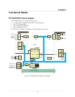
The PCI-DAS1602/12 is a multifunction measurement and control board designed for the PCI bus. This board
can be used for applications such as data acquisition, system timing, and industrial process control.
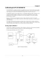
The PCI-DAS1602/12 board is completely plug and play, with no switches, jumpers or potentiometers to set.
All board addresses and interrupt sources are set with software. You calibrate the board with software that uses
programmable on-board digital potentiometers and trim D/A converters.
The PCI-DAS1602/12 provides the following features:
Eight differential inputs or 16 single-ended 12-bit analog inputs
Sample rates of up to 330 kHz
24 bits of digital I/O
Three 16-bit down-counters
100-pin high density I/O connector
Two FIFO-buffered 12-bit analog outputs with update rates of up to 250 kHz
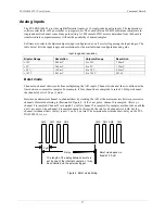
Analog input ranges are selectable via software as bipolar or unipolar. Bipolar input ranges are ±10 V, ±5 V,
±2.5 V, and ±1.25 V. Unipolar input ranges are 0 to 10 V, 0 to 5 V, 0 to 2.5 V, and 0 to 1.25 V. The PCI-
DAS1602/12 board has an analog trigger input. The trigger level and direction are software configurable.
The PCI-DAS1602/12 board has two 82C54 counter chips. Each chip contains three 16-bit down counters that
provide clock, gate, and output connections.
Software features
For information on the features of
Insta
Cal and the other software included with your PCI-DAS1602/12, refer
to the
Quick Start Guide
that shipped with your device. The
Quick Start Guide
is also available in PDF at
www.mccdaq.com/PDFmanuals/DAQ-Software-Quick-Start.pdf
for the latest software version or versions of the software supported
under less commonly used operating systems.
Summary of Contents for PCI-DAS1602
Page 1: ......


