background image

PCI-DAS1602/12 User's Guide 

Installing the PCI-DAS1602/12 

14 

1

50

2

49

51

100

52

99

100

50

51

1

Key

Key

The red stripe 
identifies pin # 1

The red stripe 
identifies pin # 51

Cable is labeled 

“Pins 51-100” 

Cable is labeled 

“Pins 1-50” 

Field Wiring connections:
SCB-50
CIO-MINI50
CIO-MINI50/DST
CIO-TERM100/DST
BNC-16DI or BNC-16SE
ISO-RACK16/P or ISO-DA02/P

with the DADP-5037 adaptor board:
CIO-ERB08 or CIO-ERB24
SSR-RACK08 or SSR-RACK24

Connect to the board’s 
100-pin I/O connector.

Pin 1 is indicated by an 
arrow   on the connector.


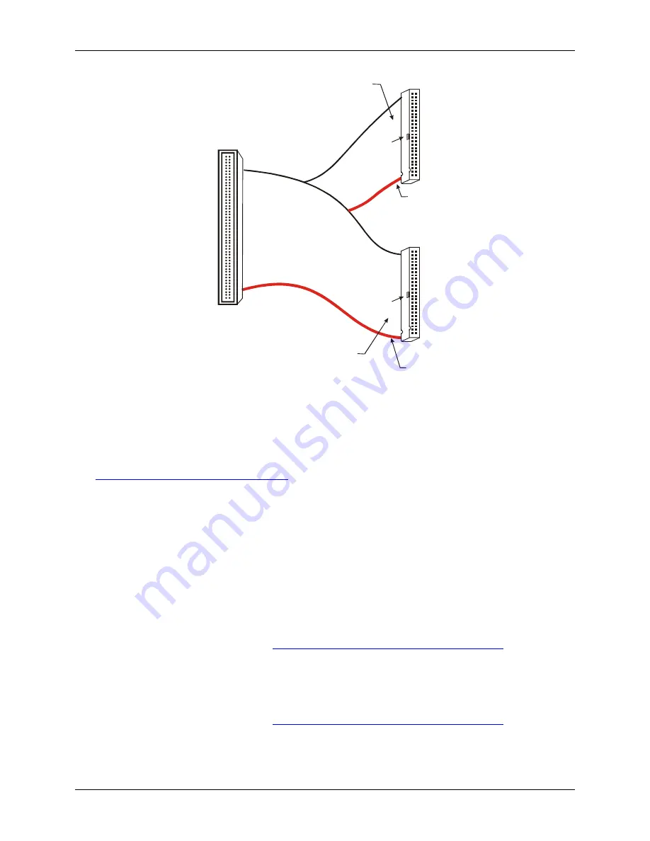
Figure 1. C100FF-x cable 

The first 50-pin connector is used primarily for analog signals (pins 1-50 of the 100-pin connector). The second 
50-pin connector is used primarily for digital I/O signals (pins 51-100 of the 100-pin connector). This 
configuration minimizes noise in the analog signal lines, and greatly simplifies field wiring and connections to 
external devices. You can purchase C100FF-x series cables from our web site at 

www.mccdaq.com/products/accessories.aspx

. 

Field wiring and signal termination 

You can use the following MCC screw terminal boards to terminate field signals and route them into the PCI-
DAS1602/12 board using the C100FF-

x

 cable: 

Screw terminal boards 


CIO-TERM100

 – 100 pin, 16 x 4 screw terminal board. 


CIO-MINI50

 – 50-pin universal screw terminal accessory. Two boards are required. 


SCB-50

 – 50-conductor, shielded signal connection/screw terminal box providing two independent 50-pin 

connections. One box is required. 

Details on these products are available at 

www.mccdaq.com/products/screw_terminal_bnc.aspx

. 

BNC connector interface boxes 


BNC-16SE

 – 16-channel single-ended BNC connector box. 


BNC-16DI

 – Eight-channel differential BNC connector box. 

Details on these products are available at 

www.mccdaq.com/products/screw_terminal_bnc.aspx

. 


Summary of Contents for PCI-DAS1602

Page 1: ......

Page 2: ...PCI DAS1602 12 Analog and Digital I O Board User s Guide Document Revision 7 March 2009 Copyright 2009 Measurement Computing Corporation...

Page 3: ...tion For specific information please refer to the terms and conditions of sale Harsh Environment Program Any Measurement Computing product that is damaged due to misuse or any reason may be eligible f...

Page 4: ...from its use No license is granted by implication or otherwise under any patent or copyrights of Measurement Computing Corporation All rights reserved No part of this publication may be reproduced st...

Page 5: ...Installing the software 10 Installing the PCI DAS1602 12 10 Configuring the PCI DAS1602 12 11 Connecting the board for I O operations 11 Connectors cables main I O connector 11 Pinout main I O connect...

Page 6: ...PCI DAS1602 12 User s Guide 5 Power consumption 26 Environmental 26 Mechanical 26 Main connector and pin out 26 Declaration of Conformity 29...

Page 7: ...ames of manuals and help topic titles and to emphasize a word or phrase For example The InstaCal installation procedure is explained in the Quick Start Guide Never touch the exposed pins or circuit co...

Page 8: ...rsal Library to control your board Only experienced programmers should try register level programming If you need to program at the register level in your application you can find more information in...

Page 9: ...bit analog inputs Sample rates of up to 330 kHz 24 bits of digital I O Three 16 bit down counters 100 pin high density I O connector Two FIFO buffered 12 bit analog outputs with update rates of up to...

Page 10: ...uick Start Guide available in PDF at www mccdaq com PDFmanuals DAQ Software Quick Start pdf This booklet supplies a brief description of the software you received with your PCI DAS1602 12 and informat...

Page 11: ...ollow the steps below Install the MCC DAQ software before you install your board The driver needed to run your board is installed with the MCC DAQ software Therefore you need to install the MCC DAQ so...

Page 12: ...atible accessory products with the C100FF x cable ISO RACK16 P ISO DA02 P BNC 16SE BNC 16DI CIO MINI50 CIO TERM100 SCB 50 SSR RACK24 DADP 5037 adaptor required SSR RACK08 DADP 5037 with TN MC78M05CT a...

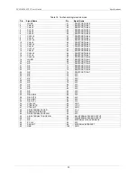
Page 13: ...82 32 n c n c 81 31 n c n c 80 30 n c n c 79 29 n c n c 78 28 n c n c 77 27 n c n c 76 26 n c n c 75 25 n c FIRSTPORTC Bit 7 74 24 n c FIRSTPORTC Bit 6 73 23 n c FIRSTPORTC Bit 5 72 22 n c FIRSTPORTC...

Page 14: ...14 HI FIRSTPORTB Bit 5 64 14 CH6 HI FIRSTPORTB Bit 4 63 13 CH13 HI FIRSTPORTB Bit 3 62 12 CH5 HI FIRSTPORTB Bit 2 61 11 CH12 HI FIRSTPORTB Bit 1 60 10 CH4 HI FIRSTPORTB Bit 0 59 9 CH11 HI FIRSTPORTA B...

Page 15: ...se in the analog signal lines and greatly simplifies field wiring and connections to external devices You can purchase C100FF x series cables from our web site at www mccdaq com products accessories a...

Page 16: ...s are available at www mccdaq com products signal_conditioning aspx Details on the DADP 5037 adapter board are available at www mccdaq com products accessories aspx Caution Before connecting signals t...

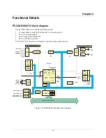
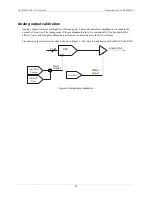
Page 17: ...Pacer Control Decode Status Int Ctl EXT PCR 10 MHz INT XINT Burst Scan XTRIG CONTROLLER FPGA Analog Trigger Logic TRIG_HI Analog Trigger TRIG_LO ADC Pacer CTR 2 CTR 1 Sample Counter CTR0 Control Gain...

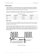
Page 18: ...61 mV 0 to 1 25 V 305 V Burst mode Channel to channel skew results from multiplexing the A D inputs Channel to channel skew is defined as the time between consecutive samples For example if four chan...

Page 19: ...eared to 0 volts on power up or reset Parallel digital I O The PCI DAS1602 12 provides 24 bits of parallel digital I O in the form of two eight bit ports and two four bit ports This digital capability...

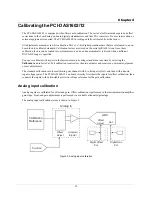
Page 20: ...tory measured voltage standards at any time by selecting the Calibrate menu in InstaCal Full calibration requires less than two minutes and requires no external equipment or user adjustments The stand...

Page 21: ...er section The tuning range of these adjustments allows for maximum DAC and output buffer offsets Coarse and fine gain calibration is performed via adjustments to the DAC reference The analog output c...

Page 22: ...trigger sources External digital A D External Trigger External analog Analog Trigger In A D triggering modes External digital Software configurable for edge triggered level activated gated Programmab...

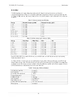
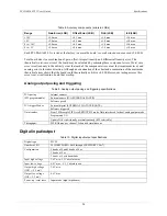
Page 23: ...0 max 1 0 max 0 75 max 1 5 max 0 to 10 V 1 0 max 1 0 max 0 75 max 1 5 max 0 to 5 V 1 0 max 1 0 max 0 75 max 1 5 max 0 to 2 5 V 1 0 max 1 0 max 0 75 max 1 5 max 0 to 1 25 V 1 0 max 1 0 max 0 75 max 1...

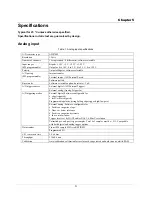
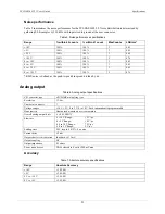
Page 24: ...k bin spread divided by 6 6 Analog output Table 6 Analog output specifications A D converter type AD7945BR multiplying type Resolution 12 bits Number of channels 2 Voltage ranges 10 V 5 V 0 to 5 V 0 t...

Page 25: ...ould theoretically exhibit a 4 4 LSB error our testing assures this error is never realized in a board that we ship Analog output pacing and triggering Table 9 Analog output pacing and triggering spec...

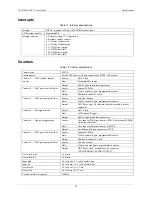
Page 26: ...r 2 output Gate Tied to counter 2 gate programmable source Output ADC Pacer clock if software selected available at user connector Counter 4 Pre trigger mode Source ADC Clock Gate A D External Trigger...

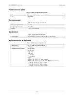
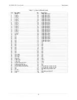
Page 27: ...al specifications Card dimensions PCI half card 174 4 mm L x 100 6 mm W x 11 65 mm H Main connector and pin out Table 16 Main connector specifications Connector type 100 pin high density Robinson Nuge...

Page 28: ...7 17 CH7 LO 67 FIRSTPORTC Bit 0 18 LLGND 68 FIRSTPORTC Bit 1 19 N C 69 FIRSTPORTC Bit 2 20 N C 70 FIRSTPORTC Bit 3 21 N C 71 FIRSTPORTC Bit 4 22 N C 72 FIRSTPORTC Bit 5 23 N C 73 FIRSTPORTC Bit 6 24 N...

Page 29: ...it 7 17 CH15 HI 67 FIRSTPORTC Bit 0 18 LLGND 68 FIRSTPORTC Bit 1 19 N C 69 FIRSTPORTC Bit 2 20 N C 70 FIRSTPORTC Bit 3 21 N C 71 FIRSTPORTC Bit 4 22 N C 72 FIRSTPORTC Bit 5 23 N C 73 FIRSTPORTC Bit 6...

Page 30: ...6 IEC 61326 1 2005 EN61000 4 2 2001 Electrostatic Discharge immunity EN61000 4 3 2002 Radiated Electromagnetic Field immunity EN61000 4 4 2004 Electric Fast Transient Burst immunity EN61000 4 5 2001 S...

Page 31: ...Measurement Computing Corporation 10 Commerce Way Suite 1008 Norton Massachusetts 02766 508 946 5100 Fax 508 946 9500 E mail info mccdaq com www mccdaq com...

Reviews: