PCI-DAS1602/12 User's Guide
Specifications
25
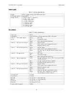
Interrupts
Table 11. Interrupt specifications
Interrupt
INTA# - mapped to IRQ
n
via PCI BIOS at boot-time
PCI Interrupt enable
Programmable
Interrupt sources
External (rising TTL edge event)
Residual sample counter
A/D end of conversion
A/D end of channel scan
A/D FIFO-not-empty
A/D FIFO-half-full
D/A FIFO-not-empty
D/A FIFO-half-full
Counters
Table 12. Counter specifications
Counter type
82C54
Configuration
Two 82C54 devices. 3 down counters per 82C54, 16 bits each
Counter 1
— ADC residual sample
counter
Source:
ADC Clock
Gate:
Programmable source
Output:
End-of-Acquisition interrupt source
Counter 2
— ADC pacer lower divider
Source:
Internal 10 MHz
Gate:
Tied to counter 3 gate, programmable source.
Output:
Chained to counter 3 clock
Counter 3
— ADC pacer upper divider
Source:
Counter 2 output
Gate:
Tied to counter 2 gate, programmable source
Output:
ADC Pacer clock (if software selected), available at user
connector
Counter 4 — Pre-trigger mode
Source:
ADC Clock
Gate:
A/D External Trigger
Output:
End-of-Acquisition interrupt source
Counter 4
— Non pre-trigger mode
Source:
User input at 100-pin connector (CLK 4) or internal 10 MHz
(software selectable)
Gate:
User input at 100-pin connector (GATE 4)
Output:
Available at 100-pin connector (OUT 4)
Counter 5 — DAC pacer lower divider
Source:
Internal 10 MHz
Gate:
Tied to counter 6 gate, programmable source.
Output:
Chained to counter 6 clock
Counter 6
— DAC pacer upper divider
Source:
Counter 5 output
Gate:
Tied to Counter 5 gate, programmable source.
Output:
DAC Pacer clock, available at user connector
(D/A INTERNAL PACER OUTPUT)
Gate width high
50 ns min
Gate width low
50 ns min
Input high
2.0 volts min, 5.5 volts absolute max
Input low
0.8 volts max, -0.5 volts absolute min
Output high
3.0 volts min @ -2.5 mA
Output low
0.4 volts max @ 2.5 mA
Crystal oscillator frequency
10 MHz
Summary of Contents for PCI-DAS1602
Page 1: ......


