background image


33 of 68 


4.4 

ENVIRONMENTAL CONDITIONS


The  device  must  be  used  while  being 
protected  from  the  weather  conditions.    The 
environments  of  operation  should  be  well 
ventilated  and  in  compliance  with  current 
legislation on hygiene and safety at work.  


CAUTION 


Do not approach the machine to 
open  flames  or  other  similar 
sources.  


Do  not  use  the  machine  in 
places  where  there  is  a  risk  of 
explosion  and fire:  the  machine 
is  not  in  compliance  with  the 
directive ATEX (ex-2014/34/EU).


Exhaust  fumes  include  carbon 
monoxide  a  dangerous  and 
deadly  gas.  Never  run  the 
engine  indoors  or  in  poorly 
ventilated premises.


4.5 

STARTING THE WORK CYCLE


After  performing  the  preliminary  checks  at 
startup  described  in  the  previous  paragraph 
(PAR.  4.3)  you  can  start  the  machine  by 
following the instructions below: 
To start the trowel the operator must: 

1.  Settle  himself  into  the  driver's  seat 

after  having  carefully  adjusted  its 

position,  placing  his  feet  on  the 
appropriate foot rest. 

2.  Make sure that the steering control is  
 

in the neutral position. 

3.  Close the choke lever (CHOKE). 
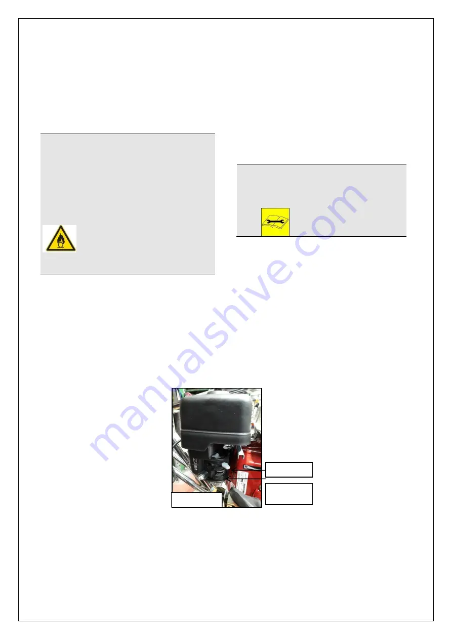
4.  Make  sure  that  the  petrol  tap  (Figure 

4.9) is in the open position. 

5.  Move the throttle lever by hand to the 

minimum position. 

6.  Turn the key to start the machine. 
7.  (For petrol engines only) After start-up 

open the choke lever (CHOKE). 


IMPORTANT! 

For  more  detailed  information  on 
start-up  procedures  refer  to  the 
engine’s instruction manual  


The  engine’s  start-up  occurs  at  low 
revs,  the  clutch  has  not  yet  triggered 
and  rotors  don't  turn  yet  (the  clutch 
triggers  at  1500  rpm).  To  avoid 
skidding  which  would  lead  to  a  high 
clutch  wear  bring the  accelerator  to  a 
value  of  up  to  2500  revolutions  per 
minute. 


Figure 4.9 

CHOKE 

PETROL 
TAP 

Summary of Contents for MK8-75

Page 1: ...80001 RIDE ON TROWELS MBW Inc 250 Hartford Rd PO Box 440 Slinger WI 53086 0440 Phone 262 644 5234 Fax 262 644 5169 E mail mbw mbw com Website www mbw com MBW UK Ltd Units 2 3 Cochrane Street Bolton BL...

Page 2: ...RATIONS NON IONIZING RADIATION 15 2 5 OPERATOR POSITIONS LAYOUT OPERATION AND MAINTENANCE AREA 16 2 6 GENERAL DESCRIPTION 16 2 7 SAFETY DEVICES 17 2 8 INFORMATION ON RESIDUAL RISKS 18 3 TRANSPORT AND...

Page 3: ...6 2 1 Replacement of blades 45 6 2 2 Unlocking of blade holder arms and of cover plate 45 6 2 3 Feather edge disc replacement 45 6 2 4 Replacement of the belt s 46 6 2 5 Engine oil filling 46 6 2 6 R...

Page 4: ...revention regulations operators must be provided with all necessary personal protection equipment P P E for their own safety safety shoes safety helmet gloves ear protectors etc Please keep the manual...

Page 5: ...has been created in reference to the provisions of the machinery directive 2006 42 EC as amended with the purpose of providing the user with a general knowledge of the machine and the information for...

Page 6: ...It is hereby declared that the machine MK8 75 trowel Serial Number Year of Construction 2018 Briefly described below The double rotating MK8 75 trowel with operator on board has been designed and buil...

Page 7: ...of 68 CHAPTER 1 1 GENERAL INFORMATION 1 1 Global aspects of security 1 2 Safety signs 1 3 Symbols and glossary 1 4 Spare parts order 1 5 Review of the manual 1 6 General terms and conditions of warran...

Page 8: ...ent operation you must select and block all power sources making sure to avoid unexpected starts 8 If the machine maintenance is not performed in accordance with instructions provided is carried out w...

Page 9: ...GN DANGER OF CUTTING AND SECTIONING OBLIGATION SIGN MANDATORY USE OF EAR PROTECTORS OBLIGATION SIGN OBLIGATION TO USE SAFETY SHOES OBLIGATION SIGN OBLIGATION TO USE AIRWAY PROTECTION In case of damage...

Page 10: ...ate number of operators to optimally carry out the operation described and deriving from a careful analysis conducted by the Manufacturer meanwhile the use of a different number of workers could preve...

Page 11: ...PARTS ORDER The order of replacement parts must clearly state the data necessary for their identification and the data shown on the machine identification plate E g Machine model Type Serial Number Y...

Page 12: ...lies to the original purchaser Our responsibility on the warranty is void if you are experiencing these situations a The original owner transfers the ownership of the machine b If changes were made to...

Page 13: ...of the machine 2 2 Intended use 2 3 Prohibited use 2 4 Technical characteristics and size noise vibrations non ionizing radiation 2 5 Operator positions layout operation and maintenance area 2 6 Gene...

Page 14: ...chine s centre of gravity An excellent view of the inspection of the processing All steering parts levers joints drive shaft reducers are protected by a tunnel whose purpose is to prevent the accumula...

Page 15: ...900 Operating weight kg 178 180 192 194 198 Weight on delivery kg 220 220 240 240 240 Engine Honda Subaru Robin Honda Robin B S Installed power kw 13 13 5 13 14 18 Starting Manual Manual Electric Elec...

Page 16: ...stment are performed with the operator in the working position The operator position figure below is also an inspection location from where it is possible to supervise the proper conduct of the work c...

Page 17: ...ey in the appropriate panel The pull up starting is also envisaged The fuel consists of unleaded petrol that reaches the carburetor from the tank after having been filtered Blade rotation in the trowe...

Page 18: ...isk that cannot be eliminated Residual risks are appropriately reported through the application of specific SAFETY SIGNS called PICTOGRAMS located at the dangerous areas The pictograms have different...

Page 19: ...19 of 68...

Page 20: ...20 of 68...

Page 21: ...21 of 68...

Page 22: ...22 of 68...

Page 23: ...23 of 68...

Page 24: ...24 of 68 CHAPTER 3 3 TRANSPORT AND LIFTING 3 1 Packing and unpacking 3 2 Lifting and handling 3 3 Transport 3 4 Check for possible damage 3 5 Storage...

Page 25: ...ifting of the case should be performed from the bottom through a means of sufficient capacity for the load to be lifted approved for a mass greater than or equal to that to be lifted The maximal weigh...

Page 26: ...ty exceeding the total weight of the machine 5 Lift the machine as close as possible to the ground and avoid oblique pulling 6 Perform displacements and maneuvers with the help of one person on the gr...

Page 27: ...t the bottom of the machine fig 3 5 a 2 Secure it with the appropriate lock fig 3 5 b 3 Perform the operation on both sides of the machine 4 The two large wheels fig 3 5 c belonging to the handling de...

Page 28: ...pany 3 5 STORAGE In case the machine is not immediately installed it is appropriate place it in an environment with characteristics equal to those of the environment of use in particular In case the s...

Page 29: ...4 4 MACHINE INSTALLATION 4 1 Installation 4 2 Initial Checks 4 3 Preliminary startup operations 4 4 Environmental conditions 4 5 Starting the work cycle 4 6 Trowel steering 4 7 Trowel stop 4 8 Restar...

Page 30: ...re placing the machine on the ground Insert the seat disassembled before packing along the mounting rails on the support plate fig 4 1 and fasten it with 4 bolts fig 4 1 a and b Tighten the nuts secur...

Page 31: ...TION It is recommended to make sure that the petrol contains no water and not to use mixtures or diesel Perform this operation in a well ventilated environment and away from possible sources of heat o...

Page 32: ...ove inwards BACKWARD 6 Reposition the joint and keep it in place by means of the clip repeating in reverse the operations previously described 7 Finally replace the cover previously removed To move th...

Page 33: ...he machine by following the instructions below To start the trowel the operator must 1 Settle himself into the driver s seat after having carefully adjusted its position placing his feet on the approp...

Page 34: ...stop the trowel movement you can simply slip the steering levers back into the rest position Chapter 5 PAR 5 5 of this manual includes the positions of the control levers and the relative displacemen...

Page 35: ...35 of 68 CHAPTER 5 5 TROWEL USAGE 5 1 Safety warnings 5 2 Surface preparation 5 3 Troweling stage 5 4 Finishing stage 5 5 Layout of controls...

Page 36: ...the feather edge discs have been properly mounted on the blades The floor will be ready for the first troweling when the footprint of the shoe heel while walking is about 2 3 mm deep in the concrete...

Page 37: ...by the weather conditions cold or warm and the amount of water present in the concrete If the concrete has hardened too fast in some areas it can be moistened by spraying water through the appropriate...

Page 38: ...38 of 68 5 5 LAYOUT OF CONTROLS...

Page 39: ...39 of 68 CHAPTER 6 6 MAINTENANCE AND REPAIR 6 1 Scheduled maintenance 6 2 Routine and additional maintenance 6 3 Notes on dismantling 6 4 Troubleshooting 6 5 Parts List 6 6 Warranty...

Page 40: ...ine bring the accelerator at idle speed by activating the accelerator lever 2 Release both control bars 3 Close the petrol tap 4 Stop the engine position the switch to the OFF 0 5 Remove the ignition...

Page 41: ...ons given in the engine manual Machine stopped Power sources disconnected Check for wear and transmission belts tension degree cardan shaft greasing Weekly Follow the procedures in PAR 6 2 4 in case o...

Page 42: ...ttom of the trowel CAUTION IT IS FORBIDDEN TO REPLACE THE GEAR BOX REFER TO THE MANUFACTURER OR THE RESELLER SPECIALIZED MAINTENANCE TECHNICIAN For a possible change of the lubricant due to leaks or f...

Page 43: ...ust be carried out exclusively by a specialised operator RESELLER AUTHORIZED DEALER Machine stopped Power sources disconnected Battery Weekly Check battery charge and water level in the elements if to...

Page 44: ...NTERVENTION At the shift start Please note the requirement to perform the checking and recording of verifications of safety components every 6 months pursuant to article 71 of the legislative decree 8...

Page 45: ...blockage of blade holding arms or of the cover plate Unlocking of the blade holding arms and of the cover plate or any replacement of the blade holding arms To unlock the blades and the cover plate r...

Page 46: ...achine off after waiting for the cooling of hot parts THE ENGINE OIL TOPPING OFF CAN BE CARRIED OUT WITH THE MACHINE IN THE WORKING POSITION 1 At first proceed by emptying the tank through unscrewing...

Page 47: ...ismantling activities there are no security related or environmental problems In case you wish to proceed with the dismantling of the various machine parts it is necessary to pay attention to their mo...

Page 48: ...trouble Unscrew the spark plug and dry it The engine speed falls Accelerator cable broken or bent Replace accelerator cable Engine trouble Contact the authorized service Dirty carburettor Contact the...

Page 49: ...ade inclination page 42 Central shaft bent blocked cover plate or cross Contact the authorized service Steering control is not perfectly vertical Adjust the position of the steering control PAR 4 2 3...

Page 50: ...50 of 68 ATTACHED WIRING DIAGRAM...

Page 51: ...51 of 68 6 5 PARTS LIST...

Page 52: ...52 of 68...

Page 53: ...53 of 68...

Page 54: ...54 of 68...

Page 55: ...55 of 68...

Page 56: ...56 of 68...

Page 57: ...57 of 68...

Page 58: ...58 of 68...

Page 59: ...59 of 68...

Page 60: ...60 of 68...

Page 61: ...61 of 68...

Page 62: ...62 of 68...

Page 63: ...63 of 68...

Page 64: ...64 of 68...

Page 65: ...65 of 68...

Page 66: ...66 of 68...

Page 67: ...67 of 68...

Page 68: ...68 6 6 WARRANTY No part of this publication may be reproduced stored in a retrieval system or transmitted in any form or by any means to third parties without the prior written consent of the Manufac...

Reviews: