background image

FUNK URBAN

 USER MANUAL

p.28

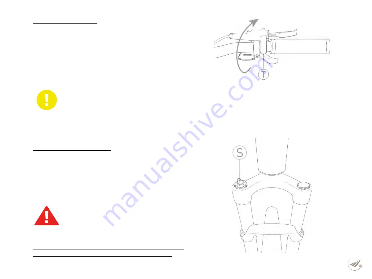
6.2.5  Brake adjustment

Adjust the  brake lever to ensure a firm grip  of the handle-
bars even during braking.
To apply  maximum braking power to the lever it  is possible  
to make the following adjustments:
- Rotate the brake lever  using the clamping screw (Ref. T - 
Figure 15) until you reach a comfortable position of the hand.

6.2.6  Suspension adjustment

At this point adjust the suspension to make the use of the     
pedal-assisted bicycle more comfortable.
Depending on  the route and the load  on the vehicle, it is pos-
sible, by means of a special manettino placed on the right 
side  of the fork (Ref. Q - Figure 14), to vary the stiffness of 
the  same.

The manufacturer is not liable for accidents resulting from in-
correct adjustment of the pedal-assisted bicycle devices.

ADJUSTMENTS

It is strictly forbidden to regulate the devices 

of the bicycle if you are not an experienced and 

educated person to do so. Incorrect regulation can 

lead to serious injuries. Therefore, if you are not 

able to regulate these functions, contact special-

ized personnel.

DANGER

FIG. 14

FIG. 15

ATTENTION

An excessive stroke of the brake lever leads to the con-

tact of the same with the knob limiting the braking action 

and causing the possible crushing of the fingers.

Summary of Contents for FUNK URBAN 20

Page 1: ...F U N K U R B A N 2 0 U S E R M A N U A L F U N K U R B A N ...

Page 2: ...ry charging 20 3 6 4 Problem solving 20 3 7 Front and rear light 21 3 8 Front suspension 21 I N D E X 4 CONDITION OF USE AND INTENDED ENVIRONMENT 22 4 1 Intended use 22 4 2 Environment of use 22 4 3 Improper uses and contraindications 23 5 LIFTING AND TRANSPORT 24 5 1 Lifting 24 5 2 Transport 24 6 COMMISSIONING 25 6 1 Battery charge 25 6 2 Preliminary functional settings 26 6 2 1 Control devices 2...

Page 3: ...F U N K U R B A N U S E R M A N U A L p 3 9 TECHNICAL ASSISTANCE AND SPARE PARTS 34 10 WAREHOUSE 34 11 DISPOSAL OF COMPONENTS AND MATERIALS 35 12 WARRANTY RULES 36 13 CONFORMITY 37 ...

Page 4: ... without this manual being automatically updated 1 2 Assistance For any inconvenience or request for clarification contact the authorized dealer who has competent and specialized per sonnel as well as specific equipment and original spare parts 1 3 Graphic form of security warnings To identify security messages the following graphical signal symbols will be used in this manual They have the functi...

Page 5: ...g instructions and safety requirements contained in this manual exempts the man ufacturer from any liability If the maintenance of the pedal assisted bicycle is carried out in a manner that does not comply with the instructions provided with non original spare parts or in any case in such a way as to compromise its integrity and modify its charac teristics the manufacturer shall will be relieved o...

Page 6: ...rators must be equipped with the necessary accident prevention equipment 3 The tools used for maintenance must be suitable and of good quality 4 Do not use gasoline or flammable solvents as detergents but always resort to non flammable and non toxic solvents 5 Limit as much as possible the use of compressed air for cleaning max 2 bar and protect yourself with glasses with side guards 6 Never resor...

Page 7: ... can generate structural breaks to the frame Adjust the height of the saddle by operating the quick release mechanism Ref A Figure 1 Check that the mechanism is tightened before testing the seat and using the medium Do not lift the saddle beyond the limit sign placed in the tube Ref B Figure 1 DANGER IMPORTANT NOTICE For your safety the reference mark of the seatpost tube B should never be outside...

Page 8: ...transport and storage of the pedal assisted bicycle it is possible to unhook and flex the steering column by means of the centrally placed hinge Ref D Figure 2 Use the hinge of the handlebar column by lifting the safety mechanism Ref E Figure 3 and open the hinge Check that the release mechanisms are tightened before us ing The vehichle ATTENTION ASSEMBLY In the event that you do not have the appr...

Page 9: ...uthorized dealer 2 6 3 Pedal mounting Right pedal IT is identified by the letter R marked on its pin For pedal mounting screw by turning the pin clockwise Figure 4 Left pedal it is identified by the letter L marked on its pin For pedal mounting screw by turning the pin counterclock wise Figure 4 ATTENTION ASSEMBLY For a correct tightening of the pedals it is neces sary to use a key of 15 ...

Page 10: ...tery and an electric motor whose intervention takes place only in conjunction with the pedaling and gradually stops as the speed of the vehicle approaches 25 km h and then stops completely at that speed For the management of the assistance system there is a special display located on the left side of the handlebar On the right side of the handlebar there is a control system for adjusting the gears...

Page 11: ...RK SUSPENSION WITH ADJUSTMENT CRANKSET 38 TEETH REAR DERAILLEUR ACERA SHIFTERS 8 SPEEDS BRAKES SHIMANO MT 200 HYDRAULIC DISKS SHIMANO RT26 ANT Ø160MM POST Ø160MM WHEELS 20 3 0 SADDLE MBM FUNK PEDAL RIGHT AND LEFT IN NON SLIP POLYMER MATERIAL LIGHTS SPANNINGA 40 LUX ENGINE CENTRAL MOTOR OLI MOVE ONE 60 NM BATTERY SEMI INTEGRATEDSPARD YT 30240 36V 7AH 252 WH MAX SERVICE SPEED 25 KM H DISPLAY LCD POW...

Page 12: ... near the wheel hubs The right le ver controls the rear brake the left one the front brake the braking action is proportional to the force applied on the lever 3 4 Speed change The pedal assisted bicycle has an 8 speed gearbox with the sprockets positioned on the rear wheel hub and selecta ble by means of the opposing levers located at the base of the right knob The indicator Ref H Figure 5 presen...

Page 13: ...button Ref L Figure 6 3 5 Assistance system management 3 5 1 Commands To manage the assistance system there is a display on the left side of the handlebar This device allows you to vary the level of assistance and to view information regarding the path and status of the battery Figure 6 FIG 6 I Display L On off button and increase the level of assistance M Mode button and reduction of the level of...

Page 14: ...ase the level of assis tance press and release the button Ref M Figure 6 The level of assistance can be selected from any screen of the display 3 5 4 Assistance level LEVEL 0 NOTHING ASSISTANCE LEVEL 1 ASSISTANCE 12 5 Recommended route plain long distances LEVEL 2 ASSISTANCE 25 Recommended route plain hilly medium long distances LEVEL 3 ASSISTANCE 50 Recommended route hilly medium climb medium dis...

Page 15: ...km h To activate the above mode turn on the assistance system using the appropriate button Ref L Figure 7 1 At this point set the assistance level to 0 and press the lever Ref N Figure 7 1 to activate the walking assistance mode Once the lever is released the assistance mode automatically turns off 3 5 7 Turning the lights on off With the device turned on press and hold the button Ref M Fig 7 1 fo...

Page 16: ...HE GRAPHICAL INTERFACE CHECK THAT THE WIRING IS INTACT AND CONNECTED CORRECTLY 0104 SPEED SENSOR NOT DETECTED CHECK THAT THE SPEED SENSOR AND MAGNET ARE CORRECTLY ALIGNED CHECK THAT THE SENSOR IS INSTALLED AND CONNECTED CORRECTLY 0105 PROBLEMS WITH THE TORQUE SENSOR SIGNAL THE TORQUE SENSOR SIGNAL IS FAULTY THE ENGINE WILL RUN AT REDUCED POWER 3 5 8 Battery indicators The state of charge of the ba...

Page 17: ...CAL BLOCKAGE OR A PROBLEM WITH THE TRANSMISSION UNIT CABLE 0809 THE BATTERY VOLTAGE IS HIGHER THAN THE MAXIMUM ALLOWED 0810 PROBLEMS WITH THE ELECTRIC CURRENT SENSOR 0811 THE CONTROL UNIT HAS DETECTED AN EXCESS OF ELECTRIC CURRENT 1101 COMMUNICATION PROBLEMS BETWEEN THE USER INTERFACE AND THE CONTROL UNIT CHECK THAT THE CABLE IS INTACT AND CONNECTED CORRECTLY 1102 ONE OF THE BUTTON PANEL KEYS GOT ...

Page 18: ...ing on the assistance system in the upper part of the battery there is a button Ref O Fig ure 8 that allows through a LED light of different colors Ref P Figure 8 to display the charge status CHARGING STATUS LED RED LIGHT 0 25 GREEN LIGHT 25 75 BLUE LIGHT 75 100 FIG 8 3 6 2 Battery removal installation For remove the battery secure who Is the system of assistance who the battery Are Off e proceed ...

Page 19: ...formed without the unlock key remove the key if inserted 2 Align the battery above the oblique pipe of the frame by matching the electrical connector Ref R Figure 10 1 Carefully insert the battery into the frame until you hear the closing click of the lock At this point the battery is already self locked FIG 10 1 2 3 ...

Page 20: ...the rubber stopper at the top right of the battery Figure 11 4 Connect the supplied battery charger with the appropriate plug 5 Connect the battery charger to a power outlet 230 V 50 Hz and charge for as long as necessary ATTENTION BATTERY CHARGER Always connect the plug to the bat tery first and then the battery charg er to the power outlet FIG 11 3 6 4 Problem solving ATTENTION TROUBLESHOOTING I...

Page 21: ...p of the fork In particular it is possible to vary the preload of the fork by rotating the manettino placed in the upper right part Ref S Figure 14 according to the characteristics of the user and the terrain F U N K U R B A N U S E R M A N U A L p 2 1 3 7 Front and rear light To ensure visibility during both day and night hours two lights are installed in the FUNK URBAN model one front Figure 12 ...

Page 22: ... outdoors in the absence of adverse weather conditions heavy rain hail snow strong wind etc Maximum permissible temperature 40 C Minimum permissible temperature 0 C Maximum permissible humidity 70 Charging temperature 0 40 C The environment of use may have an asphalted bottom or with not excessively high roughness In addition the place of use must be illuminated by the sun or by artificial lights ...

Page 23: ...r Ride the pedal assisted bicycle in areas where there is a danger of explosions Ride the pedal assisted bicycle in adverse weather conditions heavy rain hail snow strong wind etc Ride the pedal assisted bicycle under the influence of alcohol or drugs Ride the pedal assisted bicycle if your weight is higher than allowed Charge the battery in an environment that is too hot or not sufficiently venti...

Page 24: ...achieved by binding it with bands or anchor cables in good condition In this respect the coupling devices must be in stalled so as not to damage the frame and other parts of the bicycle The manufacturer is not liable for breakages due to lifting and or transporting the pedal assisted bicycle after delivery CRUSHING AND IMPACT During lifting extreme caution should be exercised to avoid damage to pe...

Page 25: ...harging is complete always disconnect the plug from the mains first and then the plug from the battery Always recharge the battery completely Always use the original supplied power supply Do not leave the battery charging longer than necessary Always recharge in a ventilated environment Do not recharge the battery in too hot environments Do not recharge the battery in the vicinity of flammable liq...

Page 26: ... ASSISTED BICYCLE Immediately activate all meas ures to carry out a proper repair and if necessary contact the authorized dealer or an authorized workshop ATTENTION Do not inflate tires beyond the permissible value reported by the manufacturer on the side surface of the tires 6 2 Preliminary functional checks Before each use the driver must ensure the safety status of the pedal assisted bicycle Th...

Page 27: ...ebar and saddle position Check that the saddle and handlebars are properly attached to the frame and positioned in the most comfortable config uration for the rider for complete control of the bicycle Otherwise before departure act on the systems for adjusting the position of the saddle and handlebars For more information on the regulation refer to section 2 6 DANGER IMPORTANT NOTICE Check that th...

Page 28: ...vehicle it is pos sible by means of a special manettino placed on the right side of the fork Ref Q Figure 14 to vary the stiffness of the same The manufacturer is not liable for accidents resulting from in correct adjustment of the pedal assisted bicycle devices ADJUSTMENTS It is strictly forbidden to regulate the devices of the bicycle if you are not an experienced and educated person to do so In...

Page 29: ...le Don t ask your pedal assisted bike for performance that s superior to what it was designed for Use the bike only in the manner and intended uses described in this manual Never ride the pedal assisted bicycle with disassembled parts The pedal assisted bicycle cannot be used on very wet icy or slippery surfaces Avoid very uneven surfaces and obstacles Ride with both hands on the handlebars Replac...

Page 30: ... It is very dan gerous to brake when cornering you may lose control of the bike 7 1 Use of the bicycle Before using the pedal assisted bicycle in places open to traffic it is advisable to familiarize yourself with the behavior of the vehicle The first uses must be made in private environments away from traffic other cyclists and obstacles of any kind The driver must adapt the driving speed of the ...

Page 31: ...he battery charger the bicycle must be supported in a stable manner using special support elements DANGER 8 2 Daily maintenance and checks 8 2 1 Tag and pictograms check Check the legibility and presence of the CE plate and the warning stickers applied to the body of the bicycle 8 2 2 Wheel control Through the special inflation valve on the rims check the inflation pressure of the tires using a co...

Page 32: ... the operation of the various components especially the electrical parts cleaning must be carried out taking some precautions It is absolutely forbidden to direct jets of pressurized water towards the electrical parts the motor and the battery for which sponge washing is recommended Before starting the pedal assisted bicycle dry completely with low pressure compressed air and check that there is n...

Page 33: ...e been switched on correctly 8 4 2 Control and adjustment of the rear derailleur Adjustment of the lower and upper limit switches of the gearbox Turn the two screws Ref U T Figure 16 so that the chain does not come out The chain shift device must be in line with both the larger and smaller gears Ref Figure 17 To prevent damage to the gearbox it is recommended not to exert too much pressure on the ...

Page 34: ...ations must be carried out Repair it in a dry and airy place Perform a general cleaning of the pedal assisted bicycle Turn off the battery remove it from the seat and store it in a special storage site fully charged and recharge it rego larmente Leave the bike on a special support Protect exposed electrical contacts with antioxidant products Grease all surfaces not protected by paints or anti corr...

Page 35: ...sal centers Divide the materials according to their nature commissioning specialized companies authorized to dispose of in compli ance with the provisions of the law 11 DISPOSAL OF COMPONENTS AND MATERIALS ATTENTION DISPOSAL OF MATERIALS The disposal of packaging waste and vacuumed dust replaced parts and or the pedal assisted bicycle as a whole at the end of its intended life must be carried out ...

Page 36: ... bicycle They will be needed the serial number and the photograph of the proof of purchase of the authorized retailer The serial number is printed on the label on the battery slide and on the battery itself Fig 19 Claims must be made through an official retailer by presenting the original tax document receipt or invoice and printing of the confirmation of activation of the warranty that you will r...

Page 37: ...rts for repair and replacement EXCLUSIONS Normal wear and tear on parts subject to it such as tires chains brakes cables and gear wheels in situations where there are no material defects Bicycles assisted by an unauthorized MBM distributor Changes from the original packaging Use of the bike for abnormal activities such as competition and or commercial activities or for purposes other than those fo...

Page 38: ...M B M S r l Unipersonale Via Emilia Levante 1671 73 75 47521 Cesena FC Tel 39 0547 300364 Fax 39 0547 304326 Email info mbmbike it W W W M B M B I K E I T ...

Reviews: