background image

Form No.3351-1A-01A

E

E-1

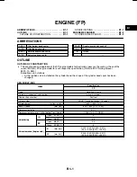
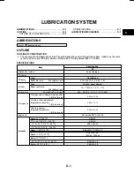
COOLING SYSTEM

ABBREVIATIONS

E-1

. . . . . . . . . . . . . . . . . . . . . . . . . . .

OUTLINE

E-1

. . . . . . . . . . . . . . . . . . . . . . . . . . . . . . . . . .

OUTLINE OF CONSTRUCTION

E-1

. . . . . . . . . . . .

SPECIFICATIONS

E-1

. . . . . . . . . . . . . . . . . . . . . . . .

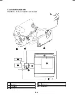
COOLING MECHANISM

E-2

. . . . . . . . . . . . . . . . . . . . .

STRUCTURAL VIEW AND COOLANT FLOW

DIAGRAM

E-2

. . . . . . . . . . . . . . . . . . . . . . . . . . . . . .

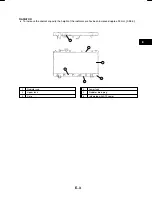
RADIATOR

E-3

. . . . . . . . . . . . . . . . . . . . . . . . . . . . . . .

ABBREVIATIONS

ATF

Automatic transaxle fluid

OUTLINE

OUTLINE OF CONSTRUCTION

FP, FP (HiĆpower)

D

The construction and operation ofthe cooling system for Australian specs. are the same as those ofthe

current 323 (BJ) FP engine model for each respective specification. (Refer to 323 Training Manual

3327-10-98G.)

Due to the change in vehicle body shape, the radiator shape has also been changed from the current 323

(BJ).

SPECIFICATIONS

Item

Specification

Item

FP

Cooling system

WaterĆcooled, forced circulation

Coolant capacity (Approximate quantity)

(L {US qt, lmp qt.})

7.5 {7.9, 6.6}

Water pump

Type

Centrifugal, VĆribbed belt driven

Type

Wax, bottomĆbypass

Thermostat

InitialĆopening temperature

(

°

C {

°

F})

80Ċ84 {176Ċ183}

Thermostat

FullĆopening temperature

(

°

C {

°

F})

95 {203}

FullĆopening lift

(mm {in})

8.5 {0.33} min.

Radiator

Type

Corrugated fin

Radiator cap opening pressure

(kPa {kgf/cm

2

, psi})

94Ċ122 {0.95Ċ1.25, 13.6Ċ17.7}

Type

Electrical

Cooling fan

Blade

Number

4

Blade

Outer diameter

mm {in}

300 {11.8}

Summary of Contents for premacy

Page 1: ...ation or advance notice All rights reserved No part of this book may be reproduced or used in any form or by any means electronic or mechanical including photocopying and recording and the use of any...

Page 2: ...IALS 323 Training Manual Australia General R H D L H D 3327 10 98G 323 Workshop Manual Supplement Europe 1633 10 98G 626 Training Manual Europe 3303 10 97D 626 Training Manual Australia General R H D...

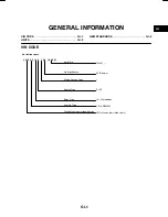
Page 3: ...DARDS GI 3 VIN CODE Australian specs J M 0 C P 0 0 1 0 0 0 0 1 JM0 Mazda Australian specs 100001 1 0 P 1 Serial No 1 P FP Model Change Code Engine Type 10 Closed body CP PREMACY Vehicle Type World Man...

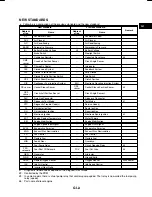
Page 4: ...n conventional units are converted from these values Rounding off D Converted values are rounded off to the same number of places as the SI unit value For example if the SI unit value is 17 2 and the...

Page 5: ...rank Angle Sensor 2 DLC Data Link Connector Diagnosis Connector DTM Diagnostic Test Mode Test Mode 1 DTC Diagnostic Trouble Code s Service Code s DI Distributor Ignition Spark Ignition DLI Distributor...

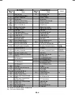
Page 6: ...n Secondary Air Injection System Pulsed injection Pump Speed Sensor NE Sensor 6 AIR Secondary Air Injection Secondary Air Injection System Inject with compressor SAPV Secondary Air Pulse Valve Reed Va...

Page 7: ...Abbrevi ation Name Abbrevi ation Name Remark VAF sensor Volume Air Flow Sensor Air flow Sensor WU TWC Warm Up Three Way Catalytic Converter Catalytic Converter 5 WOT Wide Open Throttle Fully Open 5 D...

Page 8: ...327 10 98G Exceptions are as follows As the ignition coil is installed on the cylinder head the shape of the cylinder head cover has been changed SPECIFICATIONS Item Specification Item FP Type Gasolin...

Page 9: ...CYLINDER HEAD COVER D Bosses for ignition coil installation are installed at the spark plug holes for the No 2 and No 4 cylinders on the cylinder head cover 1 Ignition coil installation position 2 Bo...

Page 10: ...ssure kPa kgf cm2 psi 450 530 4 5 5 5 64 78 Type Full flow paper element Oil filter Bypass pressure kPa kgf cm2 psi 79 110 0 8 1 2 12 17 Oil pressure kPa kgf cm2 psi rpm 400 490 4 0 5 0 57 71 3 000 Oi...

Page 11: ...VIEW AND LUBRICATION FLOW DIAGRAM 1 Oil pan 2 Oil strainer 3 Oil pump 4 Oil filter 5 Oil pressure switch 6 Orifice 7 Camshaft 8 Main bearing 9 Crankshaft 10 Connecting rod bearing 11 Oil jet 12 Pisto...

Page 12: ...l 3327 10 98G Due to the change in vehicle body shape the radiator shape has also been changed from the current 323 BJ SPECIFICATIONS Item Specification Item FP Cooling system Water cooled forced circ...

Page 13: ...E 2 COOLING MECHANISM STRUCTURAL VIEW AND COOLANT FLOW DIAGRAM 1 Coolant reservoir 2 Radiator 3 Thermostat 4 Water pump 5 Cylinder block 6 Cylinder head 7 Heater unit...

Page 14: ...ATOR D To increase the coolant capacity the height of the radiator core has been increased approx 25 mm 0 98 in 1 Radiator cap 2 Upper tank 3 Core 4 Lower tank 5 Radiator drain plug 6 Integrated with...

Page 15: ...10 STRUCTURAL VIEW F1 10 SYSTEM DIAGRAM F1 11 EXHAUST SYSTEM F1 12 OUTLINE F1 12 STRUCTURAL VIEW F1 12 EMISSION SYSTEM F1 13 OUTLINE F1 13 STRUCTURAL VIEW F1 13 SYSTEM DIAGRAM F1 14 CONTROL SYSTEM F1...

Page 16: ...PCM Powertrain control module PCV Positive crankcase ventilation PRC Pressure regulator control PSP Power steering pressure STA Start TCS Traction control system TP Throttle position TR Transaxle rang...

Page 17: ...ery Top feed Type of drive Voltage Pressure regulator Regulating pressure kPa kgf cm2 psi 280 2 9 41 Fuel pump Type Impeller in tank Fuel tank Capacity L US qt Imp qt 58 61 51 Fuel Specification Unlea...

Page 18: ...sure regulator 13 Fuel filter low pressure 14 Fuel pump 15 Fuel tank 16 Fuel filter high pressure 17 Pulsation dumper 18 Purge solenoid valve 19 EGR valve 20 VICS solenoid valve 21 VICS vacuum chamber...

Page 19: ...L 2K 1T 1O 1Q 4P 3I 4E 4F 3J ACC ON STA LOCK B ACC IG1 IG2 STA AT1 B H C G F E I D A B F A C G I D E H A B A B M P B D A C A B C D b c d e f A B C E FEN TEN KLN AT10 AT5 A C B AT10 AT5 3J 3H 3H 4O 4O...

Page 20: ...R 4J 1S 1J 1P 3C 1B 3L 3B 3E 1A A C D F A B A B A B A B A B A B A B B C A B C A A B D C A B C D b c d e f IG B A B A C B 3M 3N 1I 3A 3F 3D 3K 1M 3O 3P 4N 4T 4L 4W 4X 4Y 4Z 3M 3N 1S 1J 1P 4H 4G 4C 4A 4...

Page 21: ...tch 32 Clutch switch 33 IAC valve 34 IAT sensor 35 MAF sensor 36 CKP sensor 37 CMP sensor 38 VICS solenoid valve 39 PRC solenoid valve 40 Purge solenoid valve 41 Fuel injector No 1 42 Fuel injector No...

Page 22: ...FP Remark Fresh air duct Same as 323 BJ FP engine model Resonance chamber Same as 323 BJ FP engine model Air cleaner Same as 323 BJ FP engine model Throttle body Same as 323 BJ FP engine model Air val...

Page 23: ...purge solenoid valve 4 Throttle body 5 IAC valve 6 MAF sensor 7 Air cleaner 8 IAT sensor 9 Fresh air duct 10 Resonance chamber 11 EGR valve 12 VICS shutter valve actuator 13 VICS solenoid valve 14 VIC...

Page 24: ...model Quick release connector and plastic fuel hose Same as 323 BJ FP engine model Fuel pump Same as 323 BJ FP engine model Fuel filter high pressure Same as 323 BJ FP engine model Fuel injector Same...

Page 25: ...3 Quick release connector 4 To pulsation damper 5 From pressure regulator SYSTEM DIAGRAM 1 Fuel tank 2 Fuel filter low pressure 3 Fuel pump 4 Fuel filter high pressure 5 Pulsation damper 6 Fuel injec...

Page 26: ...STEM OUTLINE D The exhaust system is the same as that of the current 323 BJ FP engine model Refer to 323 Training Manual 3327 10 98G STRUCTURAL VIEW 1 Exhaust manifold 2 Front pipe 3 TWC 4 Presilencer...

Page 27: ...k Item PREMACY FP 323 BJ FP Remark Rollover valve Same as 323 BJ FP engine model Evaporative gas check valve two way Same as 323 BJ FP engine model Charcoal canister Same as 323 BJ FP engine model Eva...

Page 28: ...l Tank Side 1 Rollover valve built in fuel tank SYSTEM DIAGRAM 1 Rollover valve evaporative gas check valve two way integrated 2 Charcoal canister 3 Purge solenoid valve 4 EGR valve 5 PCV valve 6 TWC...

Page 29: ...witch for MTX Load no load detection Same as 323 BJ FP engine model Clutch switch for MTX Load no load detection Same as 323 BJ FP engine model TR switch for ATX Load no load detection Same as 323 BJ...

Page 30: ...l ESA control Same as 323 BJ ZL engine model EGR valve EGR control Same as 323 BJ FP engine model In EGR control operation conditions have been changed Purge solenoid valve Purge control Same as 323 B...

Page 31: ...tral switch for MTX 12 TR switch for ATX 13 PSP switch 14 Brake switch 15 Battery 16 DLC 17 VSS for MTX 18 VSS for ATX 19 IAC valve 20 VICS solenoid valve 21 Fuel injector 22 Fuel pump relay 23 Igniti...

Page 32: ...F1 18 BLOCK DIAGRAM...

Page 33: ...valve 22 Fuel injectors 23 Ignition coil 24 PRC solenoid valve 25 Fuel pump relay 26 O2S heater integrated with HO2S 27 EGR valve 28 Purge solenoid valve 29 A C relay 30 Condenser fan relay for MTX 3...

Page 34: ...sor Knock sensor HO2S vice VSS dev Neutral Clutch switch 1 put TR switch 2 In PSP switch Brake switch A C switch refrigerant pressure switch high low pressure Generator terminal P output voltage DLC t...

Page 35: ...C switch and fan switch are on 2 Headlight is on Fan switch is above 1st Cooling fan is operating and Rear window defroster is on EGR CONTROL OUTLINE D The EGR control of the PREMACY FP engine model i...

Page 36: ...witch is turned to ON position D Sets throttle opening angle for engine control closed D Fixes closed throttle position learning value to set value P0123 TP sensor Input voltage from TP sensor is abov...

Page 37: ...rcuit has malfunction D Stops IAC P1523 VICS sole noid valve Open or short circuit is observed in VICS solenoid valve system when ignition switch is turned to ON position P1602 Immobilizer t Commanded...

Page 38: ...N OFF 4T FUELPW1 Fuel injection duration ms 4W 4X 4Y 4Z First gear 1 2 3 4 GEAR Second gear 1 2 3 4 GEAR Third gear 1 2 3 4 Fourth gear 1 2 3 4 IAC IAC valve ms 4M 4O IAT IAT C 3B IAT IAT signal volta...

Page 39: ...Applicable Not applicable Simulation Definition Operation Test condition PCM terminal item Definition Operation IG ON IDLE PCM terminal ACCS A C relay ON OFF 1S ALTF Generator field coil control duty...

Page 40: ...oils for FP engines are placed in the No 2 and No 4 cylinders on the upside of the cylinder head cover They are the same types as those of the current 323 BJ ZL and ZM engines SPECIFICATIONS Item Spec...

Page 41: ...G 2 STRUCTURAL VIEW 1 Battery 2 Generator 3 Ignition coil 4 Spark plug 5 High tension lead 6 Starter...

Page 42: ...Engine Item FP Clutch control Hydraulic Clutch cover Spring type Diaphragm Clutch cover Set load N kgf lbf 4 805 490 1 080 Clutch disc Outer diameter mm in 200 7 87 Clutch disc Inner diameter mm in 1...

Page 43: ...J1 J1 1 MANUAL TRANSAXLE F25M R OUTLINE J1 2 OUTLINE OF CONSTRUCTION J1 2 SPECIFICATIONS J1 2...

Page 44: ...98G SPECIFICATIONS Item Engine Item FP Transaxle type F25M R Transaxle control Floor shift Operation system Rod Shift assist Forward Synchromesh Shift assist Reverse Selective sliding and synchromesh...

Page 45: ...OUTLINE K 9 CONSTRUCTION K 9 BLOCK DIAGRAM K 10 ELECTRONIC CONTROL ITEMS AND CONTENTS K 11 COMPONENT DESCRIPTIONS ELECTRONIC CONTROL K 11 INPUT OUTPUT SIGNALS AND RELATED CONTROLS K 12 SHIFT MECHANIS...

Page 46: ...K 2 OUTLINE OUTLINE OF CONSTRUCTION D The construction and operation of the automatic transaxle is the same as that of the current 323 BJ Refer to Mazda 323 Training Manual 3327 10 98G...

Page 47: ...plates 3 3 Hydraulic system Reverse clutch number of drive driven plates 2 2 Low and reverse brake number of drive driven plates 5 5 Band servo Servo diameter piston outer dia mm in 64 6 2 54 Front p...

Page 48: ...atic transaxle is the same as that of the current 323 BJ CROSS SECTIONAL VIEW 1 Torque converter 2 Oil pump 3 Forward clutch 4 Front planetary gear 5 Rear planetary gear 6 3 4 clutch 7 Reverse clutch...

Page 49: ...OFF type solenoids shift solenoids D and E And the clutch engagement pressure is controlled by the duty cycle type solenoids shift solenoids A B and C Powertrain mechanism D The driving force from the...

Page 50: ...EN OPEN CLOSE OFF OFF HOL D 3GR 1 000 OPEN OPEN OPEN OFF OFF S 4GR 3 0 725 CLOSE OPEN OPEN ON OFF HOL 2GR 1 497 OPEN OPEN CLOSE OFF OFF HOL D 3GR 3 1 000 OPEN OPEN OPEN OFF OFF D 4GR 3 0 725 CLOSE OPE...

Reviews: