background image


Navigation Functions (optional):


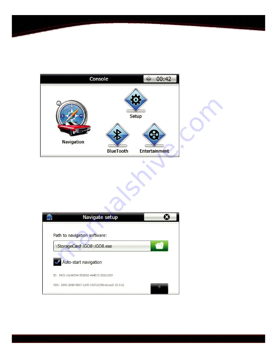
When switching to navigation the main menu will be shown.


To setup up navigation press the "Navigation" icon. If first time use it will take 
you to page where user can select default path for the navigation software 
through the SD card. Select the ".exe" file for the navigation software. Select 
auto-start option if user do not want to set every time. This will execute the 
".exe" file path on entering Navigation mode.


Summary of Contents for CI-VL2-MAZDA3

Page 1: ...CI VL2 MAZDA3 Installation Manual Product Name CI VL2 MAZDA3 Product Type Video Interface with optional build in navigation Application All Mazda 2014 2015 cars with new Mazda Connect systems...

Page 2: ...he box Item Qty Description Part No 1 1 Video Interface 2 1 Power Interface Harness 3 1 Audio RCA Cable 4 1 Video RCA Cable 5 1 LVDS Cable 6 1 Relay Interface Cable 7 1 Speaker optional 8 1 GPS Antenn...

Page 3: ...plug and play All connectors are easy to install It has built in high speed navigation module which is compatible with all new navigation software s like IGO Sygic etc OEM touch screen can be used to...

Page 4: ...nnections Diagram GPS Antenna SD Card Video RCA Connect behind LCD Audio RCA LVDS Cable GPS Speaker Connect behind CD unit Interface Power CTRL Port Connect Connect to ACC behind and Reverse LCD Trigg...

Page 5: ...How to connect Power cable Connect the Yellow and Red wire together to Connect to Reverse trigger Connect separate GREY ACC of the Car of car reverse light wire here...

Page 6: ...d Box provided as optional The Android box has powerful hardware and customized UI for optimized use in a car while driving The Camera can be connected using the Video RCA cable provided Red Backup ca...

Page 7: ...Set On Once for IR Set off for normal use UP OFF programming and ON OFF 5 touch calibration is for times for touch panel DVD TV for Video1 and calibration Video2 7 8 No Function Keep UP OFF in all ca...

Page 8: ...ghtness Set the Brightness of each video source O Saturation Set the saturation of each video source O Position H Set the horizontal position of each video source O Position V Set the vertical positio...

Page 9: ...the 7 th Pin 5V_SW this pin can output 5V with 1A max which is enough for a relay pull when in inserted video this pin 5V when in OEM video this pin 0V 5 the 8 th Pin 5V_AV1 2 this pin can output 5V w...

Page 10: ...Reverse control wire 5v will switch it to camera mode All wires can tolerate 12V for 10 seconds 5 Normal Power consumption 4 8W 6 Standby current 10uA 7 Reverse trigger threshold 5V trigger 8 Work tem...

Page 11: ...e Navigation icon If first time use it will take you to page where user can select default path for the navigation software through the SD card Select the exe file for the navigation software Select a...

Page 12: ...file O GPS monitor Used to check the GPS signal If no signals shown set COM port to COM2 The Baud rate is automatically set O System Setup Used to change the display language and switch effects O Touc...

Page 13: ...iles for multimedia are stored on usb and can be accessed using mini USB to USB hub cable The functions of multimedia are used through the touch screen For upgrade of software for navigation module in...

Page 14: ...you can adjust the image s horizontal and vertical position 2 Black screen when switching to reverse Check whether the relay interface cable installed correctly 3 The parking guideline not be display...

Page 15: ...ition RGB input for the interface Connect to Power from CAN box ACC and GROUND Connect to AUX for OEM speakers Connect to RGB of Interface The HDMI in can be used to connect to phones directly phones...

Page 16: ...on interface Connect the red and black power cable to ACC and GND from CAN box to give power to the converter Make sure to select the DIP4 on interface to be OFF and DIP1 on interface should be ON The...

Reviews: