


12
Main Power Inlet Connection
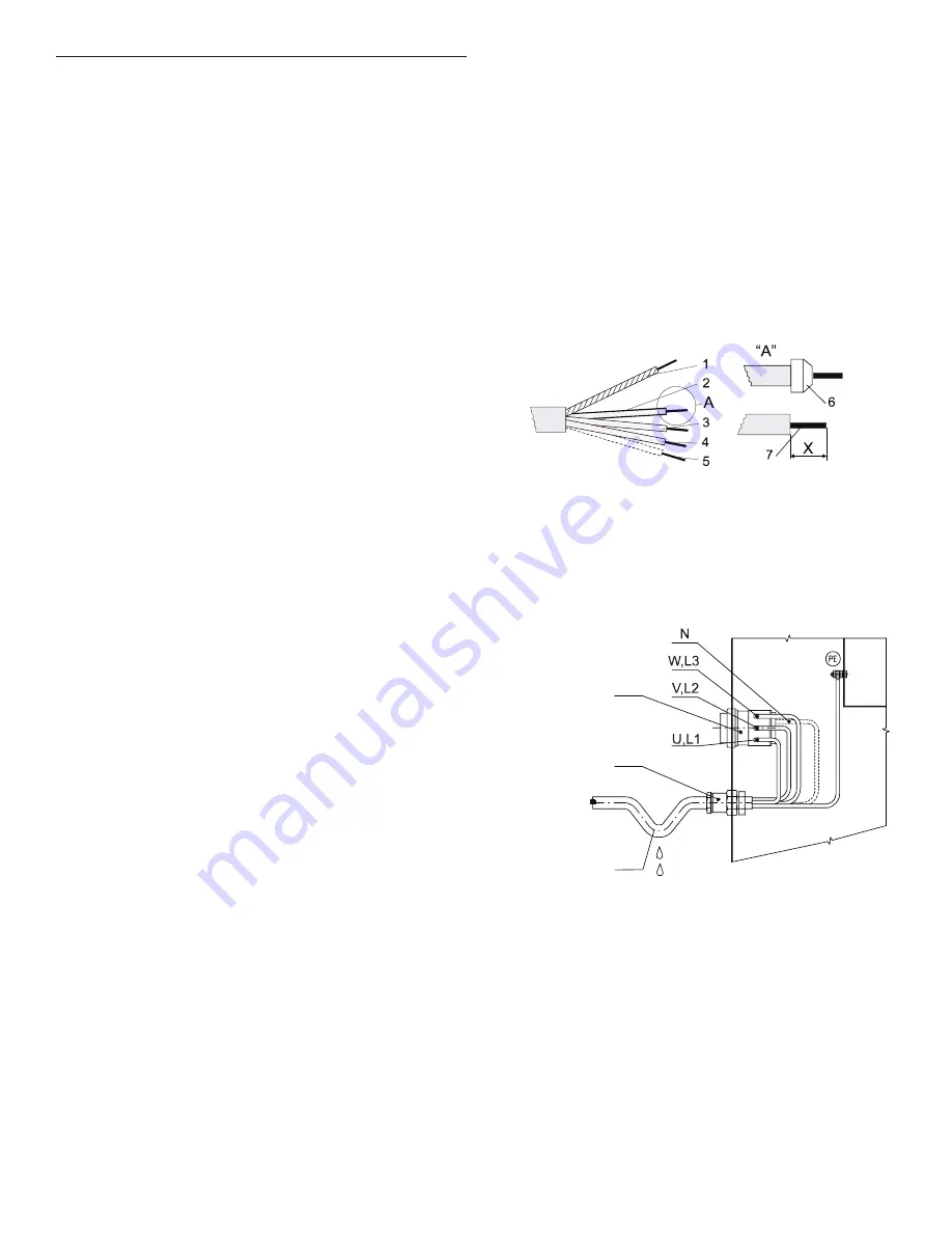
Adaptation of Conductor Ends of Supply Cable
1. Protective conductor
(ground)
2. Phase conductor
3. Phase conductor
4. Phase conductor
5. Neutral conductor
6. Wire-end tube
7. The stripped length
of conductors
Residual Current Device (RCD)
In some locations an RCD is known as an “earth leakage trip,”
“Ground Fault Circuit Interrupter” (GFCI), “Appliance Leakage
Current Interrupter” (ALCI), or “earth (ground) leakage current
breaker.”
Specifications:
■
Tripping current: 100mA (if locally not available use a 30mA trip
current, preferably selective type with small time delay set).
■
Install a maximum of two (2) washers on each RCD (for 30mA,
only one (1) washer)
■
Type B. There are components inside the washer which use
DC-voltages, making a “Type B” RCD necessary.
When locally allowed, an RCD must always be installed. In some
electrical network earthing systems (IT, TN-C,…), an RCD might not
be allowed (see also IEC 60364).
The washer control circuits are mostly supplied by a separating
transformer. Therefore, the RCD may not detect faults in the control
circuits (but the fuse(s) of the separating transformer will).
Supply Protection Device
A supply protection device keeps the washer and wiring from
experiencing overloads and short circuits. As a supply protection
device, you can use either glow-wire fuses or automatic circuit
breakers. See “Technical Specifications” for the rating of the nominal
current and other specifications of the supply protection device.
This table specifies that protection must be the “slow” type, curve D
for circuit breakers. Although not recommended, if you cannot use
a “slow” type, select the protection device with one (1) step higher
nominal current rating to avoid disconnecting during start-up.
Supply Cable
The supply cable is not delivered with the washer.
Specifications:
■
Use conductors with copper cores.
■
Stranded conductors (flexible wiring) are strongly recommended
to avoid conductor breaking due to vibration.
■
The cross section depends on the used supply protection
device. See “Manufacturer’s Recommended Minimal Conductor
Section” in “Electrical Requirements” for the minimal cross
section.
■
The cable should be as short as possible, directly across from
the supply protection device to the washer without branching off.
■
Do not use a plug or extension cords; the washer is intended to
be permanently connected to the electrical network.
Connection:
■
Insert the cable through the hole on the rear panel.
Use a strain relief to secure the supply cable.
■
Strip the conductor ends according to “Adaptation of Conductor
Ends of Supply Cable” illustration on the right.
■
The protective conductor must be longer to ensure it is the last
one disconnected if the cable is pulled out unintentionally.
■
With stranded conductors, it is recommended to use “wire-end
tubes” with an insulated sleeve (6) for L1/U, (L2/V), (L3/W), (N)
conductors. Make sure there cannot be unintentional contact,
since the supply cable stays under voltage even when the main
switch is off.
■
Crimp a ring terminal (eyelet) to the protective conductor
(ground) for good connection to the PE terminal.
■
Connect the supply cable conductors to the terminals
(main switch [1]) marked with L1/U, (L2/V), (L3/W), (N),
and the terminal (copper screw) marked with PE.
See “Main Power Inlet Connection” illustration below.
■
Provide a sag in the cable, in front of the cable strain relief.
This will stop condensed water from entering the washer.
See “Main Power Inlet Connection” illustration below.
1. Main switch
2. Strain relief
3. Sag of inlet cable
1
2
3
Electrical Connection (cont.)