


3
INSTALLATION REQUIREMENTS
Tools, Parts, and Equipment
Read and follow the instructions provided with any tools listed
here.
Tools Needed
Washers must be installed by professional installers, who
should have a full compliment of standard SAE and metric hand
tools, and specialized tools as required. Gather the required
tools and parts before starting installation.
Additional Materials
Additional materials may be required for this type of installation
and the customer is responsible for supplying additional
hardware and adapters as necessary.
Parts Supplied
Remove parts bag from washer drum. Check that all parts were
included. The number of parts supplied varies with model.
■
Molded rubber drain hose and band clamp (2 each)
■
Rubber washers for the hoses (4)
■
Water supply hoses (2)
Equipment for Handling, Transport, and Storage
Use a lift truck or a manual skid cart for handling the washer
when it still is in the packaging material.
■
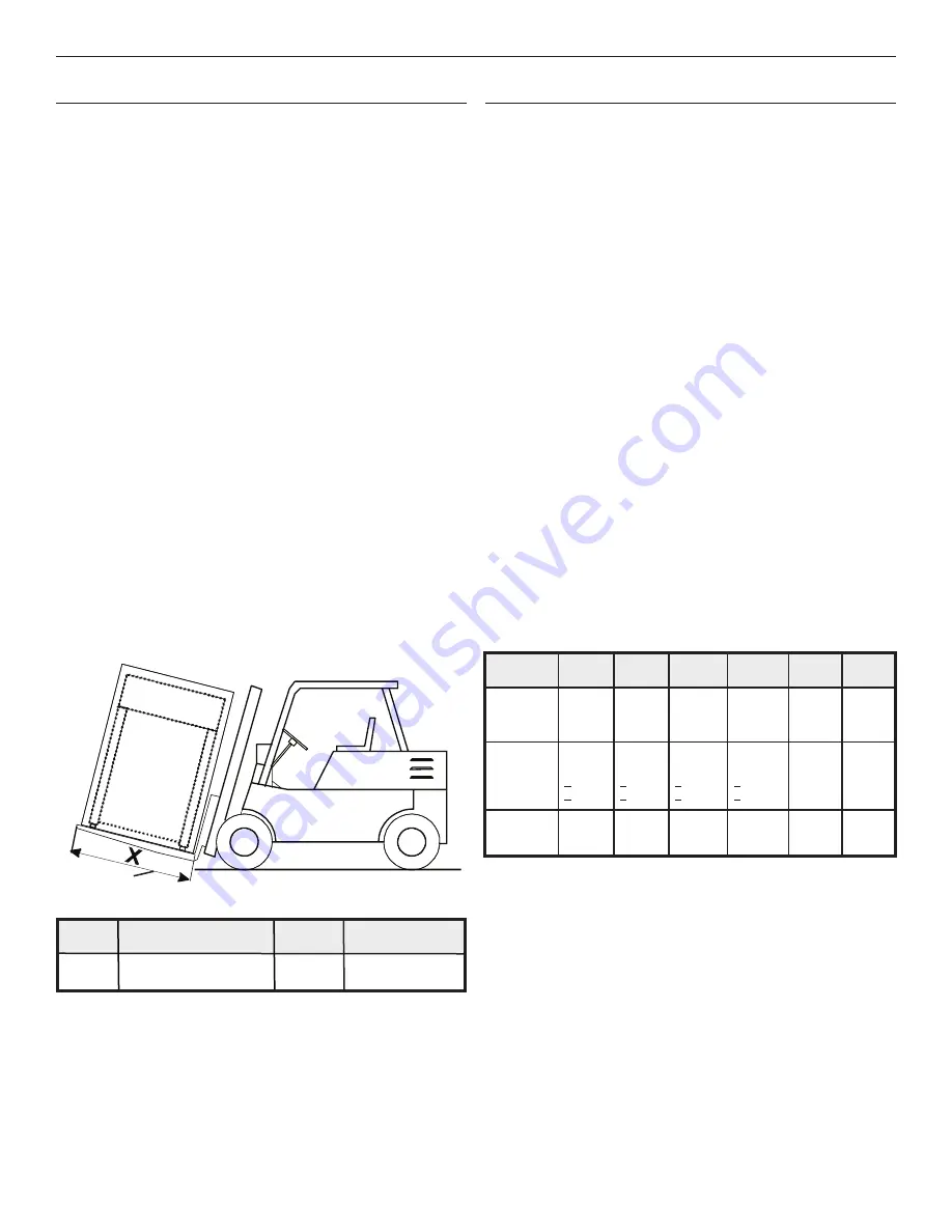
The lift truck forks must be at least 4" (100 mm) longer
than the length of the washer frame.
Location Requirements
Washers must be installed on a level concrete floor on the
ground level of a building. Washers should not be installed on a
floor other than the ground floor, or in a room with a basement
or on a floor with rooms below without approval of a structural
engineer.
Proper installation is your responsibility and must meet all
governing codes and ordinances.
Working Conditions
■
Washers should not be installed within reach of spraying
water.
■
Do not install washer where it will be exposed to weather or
excessive humidity. Do not allow water or condensation to
run over walls or floor under washer. Ambient temperature
for storage or transportation must be between -13 and 131°F
(-25 and 55°C).
Floor
Space requirements for installations are determined by
the number of washers being installed. See “Technical
Specifications” and “Installation Instructions” for more detailed
information.
■
Installation must be on a solid concrete floor or slab capable
of withstanding the weight and vibration produced by the
washer. The maximum slope of the floor is 1° under the
washer. A rough, uncovered concrete surface is preferable
to a smooth or covered surface.
Required Fork Length Chart
X - fork length
59"
71"
79"
1500 mm
1800 mm
2000 mm
80 lbs/100 lbs/125 lbs 180 lbs
230 lbs/275 lbs
(33 kg/40 kg/55 kg)
(80 kg)
(104 kg/125 kg)
Fork
Length
■
If possible, leave the washer in the packaging or on wooden
skid until foundation is prepared for installation. Washer is
attached to skid by four (4) M-16 bolts.
■
See “Moving to Final Location” for more information on
moving washer to its final location.
X
■
A hot water heater set at 158°F (70°C).
■
1" (25 mm) inlet valves for hot and cold water. Determine
water hardness levels. Hard or medium levels may require
a water softener.
■
A dedicated, GFCI-equipped circuit for each washer
(see “Electrical Requirements”).
Water and Electric
■
Washer must be secured with four (4) M16 x 160 mm
anchoring bolts. Install all four anchors before final
installation of the washer. Apply a torque of 210 Nm/
155 ft. lbs.
■
Washer will be firmly secured to the floor and all four (4)
footings must touch the floor.
■
Allow for adequate sanitary sewer drainage, located
behind the washers.
Weight of Washers
Weight on
floor
80 lbs
33 kg
100 lbs
40 kg
125 lbs
55 kg
180 lbs
80 kg
230 lbs
104 kg
275 lbs
125 kg
Maximum
static load
(with linen and
water)
3239 lbs
1469 kg
4083 lbs
1852 kg
4400 lbs
1996 kg
7144 lbs
3241 kg
–
–
Maximum
dynamic
load
(alt.
stress when
extracting)
2855 lbs
1295 kg
+616 lbs
+279 kg
3615 lbs
1640 kg
+661 lbs
+300 kg
3835 lbs
1740 kg
+704 lbs
+319 kg
6176 lbs
2801 kg
+1511 lbs
+685 kg
–
–
Dynamic
load
frequency
14.0 Hz 14.0 Hz 14.0 Hz
12.5 Hz
–
–