background image

25

HIGH VOLTAGE!

 DISCONNECT ALL POWER BEFORE SERVICING.

MULTIPLE POWER SOURCES MAY BE PRESENT. FAILURE TO DO SO

MAY CAUSE PROPERTY DAMAGE, PERSONAL INJURY OR DEATH.

WARNING

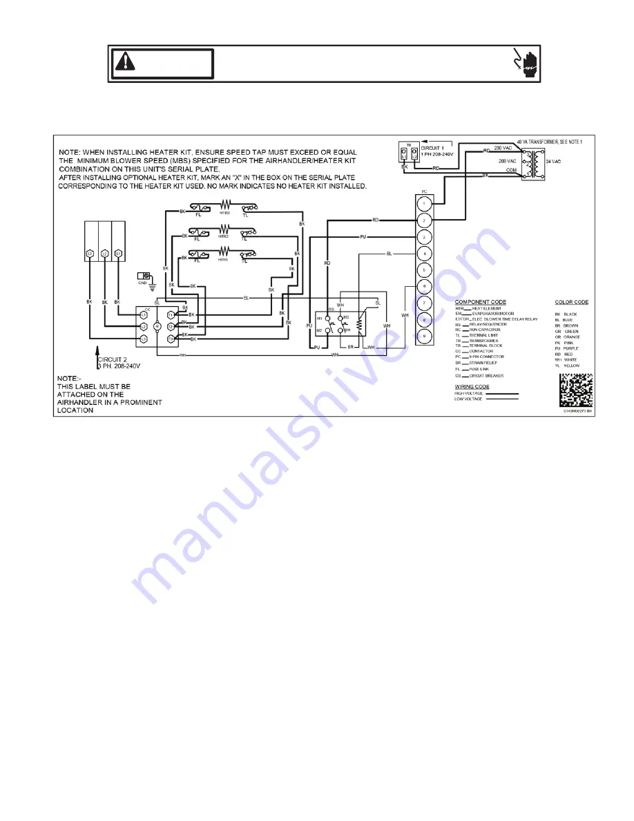
3-Phase Heat Kit

Wiring is subject to change. Always refer to the wiring diagram on the unit for the most up-to-date wiring.

Summary of Contents for Amana ARUF 14 Series

Page 1: ...ostats 14 12 6 Speed Tap Adjustment 14 13 Achieving 1 4 Low Leakage Rate 15 14 Start Up Procedure 15 15 Regular Maintenance 15 16 Airflow Data 16 17 Air Handler Low Voltage Connections 18 18 Wiring Di...

Page 2: ...or air handler is opera ng in any mode B10259 216 CO can cause serious illness including permanent brain damage or death Los equipos aparatos que producen mon xido tal como autom vil calentador de gas...

Page 3: ...consult the white business pages the yellow page section of the local tele phone book or contact HOMEOWNER SUPPORT GOODMAN MANUFACTURING COMPANY L P 19001 KERMIER ROAD WALLER TEXAS 77484 855 770 5678...

Page 4: ...scription Drain Port Plug DRAIN PORT PLUG KIT Table 1 Drip Pan Extension Side Drain Pan Screw B b A Main Drain Pan Drip Shield Bracket Drip Shield Pn a SIDE DRAIN PAN REMOVAL Figure 1 6 1 Upflow Insta...

Page 5: ...TO PULL THE COIL ASSEMBLY OUT FAIL URE TO DO SO MAY RESULT IN BRAZE JOINT DAMAGE AND LEAKS 3 Removal of the center support is required on units with 21 wide cabinet Remove and retain the two 2 screws...

Page 6: ...se clean gloves when handling coil assemblies 7 3 Special Instructions Units without a factory installed TXV come equipped with a flowrator piston for refrigerant expansion For most in stallations wit...

Page 7: ...alls Failure to do so will result in improper condensate drainage COIL INSTALLATION FOR DOWNFLOW Figure 8 Coil slides on the down ow bracket Upper Tie Plate Control Deck Down ow Bracket Center Support...

Page 8: ...tes possible leak 3 Replace the refrigerant tubing panel 4 Remove the spin closure on both the liquid and suction tubes using a tubing cutter 5 Insert liquid line set into liquid tube expansion and sl...

Page 9: ...finger tight SUBCOOL FORMULA SAT LIQUID LINE TEMP LIQUID LINE TEMP SUPERHEAT FORMULA SUCT LINE TEMP SAT SUCT TEMP NOTE Expansion valve system in ASPT models are already tuned for 16 SEER single stage...

Page 10: ...in high static pressure applications may require a deeper field constructed P style trap than is shown in Figure 12 to allow proper drainage and prevent condensate overflow Air Handler 3 MIN POSITIVE...

Page 11: ...indicated above the following formula is to be used TR kW x 3412 x Voltage Correction 1 08XCFM Where TR Temperature Rise kW Heater Kit Actual kW 3412 Btu per kW VC 96 230 Supply Volts 92 220 Supply V...

Page 12: ...pply to the unit The supply voltage must be measured and be in agreement with the unit nameplate power requirements and within the range shown 12 2 Wire Sizing Wire size is important to the operation...

Page 13: ...HEATER KITS Table 8 MINIMUM HEATER KIT AIRFLOW Table 9 3 5 6 8 10 15 19 20 25 ASPT25B14 715 715 715 715 850 ASPT29B14 715 715 715 715 875 1050 ASPT35B14 715 715 715 715 875 1050 ASPT37B14 715 715 715...

Page 14: ...aker Heat Kit The air handler has soft plastic cover on the upper ac cess panel and can be removed to allow the heater kit circuit breaker to be installed The circuit breakers have lugs for power supp...

Page 15: ...NG HIGH VOLTAGE DISCONNECT ALL POWER BEFORE SERVICING OR INSTALLING THIS UNIT MULTIPLE POWER SOURCES MAY BE PRESENT FAILURE TO DO SO MAY CAUSE PROPERTY DAMAGE PERSON AL INJURY OR DEATH Prior to start...

Page 16: ...0 1210 1105 HIGH 1785 1735 1680 1625 1555 1440 1330 LOW 1410 1360 1290 1210 1120 1010 920 MED 1610 1540 1470 1390 1300 1190 1060 HIGH 1900 1830 1740 1645 1540 1420 1280 LOW 1420 1370 1310 1240 1125 10...

Page 17: ...5 5 8 5 0 9 5 5 9 0 0 0 1 0 5 0 1 0 1 1 1 3 T 0 1 0 1 5 5 0 1 5 9 0 1 5 3 1 1 0 8 1 1 0 2 2 1 0 6 2 1 0 1 3 1 0 6 3 1 4 T 0 6 2 1 5 9 2 1 0 3 3 1 0 7 3 1 5 9 3 1 5 3 4 1 5 7 4 1 5 1 5 1 0 6 5 1 5 T 0...

Page 18: ...the connections between room ther mostat and the air handlers and the connections between the air handlers and the Condensing Unit or Heat Pump with optional connections to Outdoor Thermostats For ea...

Page 19: ...CONDENSING UNIT 24V CONNECTIONS 18 GA 2 WIRES BLUE WHITE GREEN RED CONTACTOR COIL ARUF UNIT Low Voltage Wiring Diagram for Cooling Unit with optional heat kit 10KW and below W2 GREEN RED WHITE BLUE B...

Page 20: ...FALL RED GREEN WHITE BLUE AR UNIT R Y O W BL 18 GA 5 WIRE 18 GA 7 WIRE NOTE R G BR W BL R R I B 18 GA 6 WIRE NEEDED WHEN OT IS USED R 18 GA 7 WIRE NEEDED WHEN TWO OT S ARE USED 18 GA 5 WIRE BL O W Y...

Page 21: ...OR CODES RD RED YL YELLOW BL BLUE BR BROWN OR ORANGE WH WHITE COOLING UNIT WITH OPTIONAL HEAT KITS OF 10 kW AND BELOW G R C W1 Y W W2 Y2 Y1 O G R TB YL BL TO CONDENSING UNIT 24V CONNECTION BL YL YL WH...

Page 22: ...ERGENCY HEAT RELAY OPTIONAL COLOR CODES RD RED YL YELLOW BL BLUE BR BROWN OR ORANGE WH WHITE G C R HEAT PUMP UNIT WITH OPTIONAL HEAT KITS OF 10 kW AND BELOW C W1 W2 Y2 Y1 O G R TB 18 GA 7 WIRE O Y C W...

Page 23: ...conds after 24VAC is applied to G After 24VAC is removed from G the blower motor output is de energized after a delay of 65 seconds Normal Time Delays 60Hz 50Hz Turn On Delay 7 0 SEC 1 8 4 SEC 1 Turn...

Page 24: ...TDR 4 BROWN AND WHITE WIRES ARE USED WITH HEAT KITS ONLY 5 EBTDR HAS A 7 SECOND ON DELAY WHEN G IS ENERGIZED AND A 65 SECOND OFF DELAY WHEN G IS DE ENERGIZED 6 LOW VOLTAGE FIELD WIRING TO BE N E C CLA...

Page 25: ...ERVICING MULTIPLE POWER SOURCES MAY BE PRESENT FAILURE TO DO SO MAY CAUSE PROPERTY DAMAGE PERSONAL INJURY OR DEATH WARNING 3 Phase Heat Kit Wiring is subject to change Always refer to the wiring diagr...

Page 26: ...at con tain corrosive chemicals including but not limited to chlo rine and hydroxides should not be used AIR HANDLER AIR HANDLER HOMEOWNER S ROUTINE MAINTENANCE RECOMMENDATIONS An alternate cleaning m...

Page 27: ...27 THIS PAGE LEFT BLANK INTENTIONALLY...

Page 28: ...Though not required to get the protection of the standard warranty registering your product is a relatively short process and entitles you to additional warranty protection except that failure by Cali...

Reviews: