Maytag Commercial MYR20 Installation Instructions Manual Download Page 14

14

ELECTRICAL CONNECTION

Connection to Washer:

The washer must be electrically grounded in accordance with all 

local codes or, in the absence of local codes, with the National 

Electrical Code, ANSI/NFPA 70, latest edition, or Canadian 

Electrical Code, CSA C22.1

Direct Wire Installation:

Power supply cable must match power supply (3-wire) and be:


͜

To access the disconnect, lift the top cover and support it 

with the prop rod.


͜

Copper wire of appropriate gauge for amperage requirement 

(see “Manufacturer’s Recommended Minimal Conductor 

section”). Solid wire is recommended. Do not use aluminum 

wire.


͜

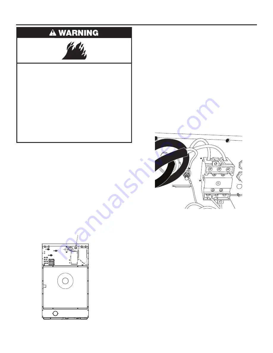
Flexible armored cable or flexible conduit must be used 

for the supply connections. Use the hole in the rear of the 

washer for routing. Connection is made directly to the 

disconnect switch inside the back top panel of the washer. 

The Aluminum Lug for Ground is next to that disconnect 

body. A Flat-head screwdriver can be used for the power 

wires to the disconnect as well as the ground to the 

lug. Incoming service wires are applied to the top of the 

disconnect body. If the washer is single phase, (only  

2 power wires) the outside positions of the disconnect 

should be used (leaving the center pole empty). Tighten 

down all connections including the unused position in the 

single-phase service case. Leaving a small radius of slack for 

the wires inside the washer, check that the cable is well held 

in place.


͜

Check the rating plate on the washer. Make sure that the 

supply phase and voltage match the rating of the washer. 

Some locations require an autonomous power switch (I) at 

the current input, with a minimum of 0.12" (3 mm) between 

contacts. Fit a 300 mA, type A, immediate response 

differential protection. Check your local regulations. Insert 

the flexible armored cable or flexible conduit through the 

hole in the rear panel. Secure the armored cable or conduit 

to the rear panel. Connect the wiring per the correct 

illustration.

 Fire Hazard

Use appropriate gauge of solid copper wire. (See chart 

in “Electrical Requirements” section).
Use a UL listed strain relief.
Disconnect power before making electrical connections.
Connect neutral wire (white) to terminal (N).
Ground wire (green or bare wire) must be connected 

to ground connector (PE). 
Connect remaining 3 supply wires to remaining 

3 terminals (L1, L2 and L3).
Securely tighten all electrical connections.
Failure to do so can result in death, fire, or 

electrical shock.

Knock out for 
Electrical Connection

PE

L1

L2

Single Phase

Summary of Contents for MYR20

Page 1: ...INSTALLATION INSTRUCTIONS COMMERCIAL WASHER EXTRACTOR MYR20 MYR25 MYR30 MYR40 MYR55 MYR65 MYS20 MYS30 MYS40 MYS55 MYS65 www maytagcommerciallaundry com WFR124390H ...

Page 2: ... 8 LOCATION REQUIREMENTS 8 ELECTRICAL REQUIREMENTS 9 FLOOR REQUIREMENTS 10 INSTALLATION OF THE WASHER EXTRACTOR WITHOUT PEDESTAL BASE 11 INSTALLATION OF THE RIGID WASHER EXTRACTOR WITHOUT PEDESTAL BASE 12 INSTALLATION INSTRUCTION 13 ELECTRICAL CONNECTION 14 WASHER MAINTENANCE 16 WARRANTY 17 WASHER SAFETY ...

Page 3: ...n soaked in or spotted with gasoline dry cleaning substances as they give off vapors that could ignite or explode Do not add gasoline dry cleaning substances to the wash water These substances give off vapors that could ignite or explode Under certain conditions hydrogen gas may be produced in a hot water system that has not been used for 2 weeks or more HYDROGEN GAS IS EXPLOSIVE If the hot water ...

Page 4: ...mensions C D A E B A B C D E Model Width mm in Door Opening mm in Depth mm in Height mm in Door Height mm in MYR20 660 26 328 12 9 686 27 1 112 43 8 425 16 8 MYR25 750 29 5 410 16 1 725 28 5 1 222 48 1 419 16 5 MYR30 750 29 5 410 16 1 840 33 1 1 222 48 1 419 16 5 MYR40 890 35 0 459 18 1 876 34 5 1 410 55 5 537 21 2 MYR55 890 35 0 459 18 1 1 011 39 8 1 410 55 5 537 21 2 MYR65 890 35 0 459 18 1 1 08...

Page 5: ...75 6 8 175 6 8 175 6 8 D2 mm in 927 36 5 1 035 40 8 1 035 40 8 1 224 48 2 1 224 48 2 1 224 48 2 E1 mm in 168 6 6 213 8 4 213 8 4 283 11 1 283 11 1 283 11 1 E2 mm in 95 3 7 95 3 7 95 3 7 133 5 2 133 5 2 133 5 2 E3 mm in 70 2 8 70 2 8 70 2 8 70 2 8 70 2 8 70 2 8 F1 mm in 60 2 3 70 2 7 70 2 7 70 2 7 70 2 7 70 2 7 F2 mm in 826 32 5 937 36 9 937 36 9 1 095 43 1 1 095 43 1 1 095 43 1 G1 mm in 368 14 5 4...

Page 6: ...52 2 D1 mm in 146 5 8 146 5 8 175 6 9 175 6 9 175 6 9 D2 mm in 930 36 7 1 041 41 1 228 48 8 1 228 48 8 1 228 48 8 E1 mm in 229 9 229 9 270 10 7 270 10 7 270 10 7 E2 mm in 90 3 5 90 3 5 111 4 4 111 4 4 111 4 4 E3 mm in 70 2 8 70 2 8 70 2 8 70 2 8 70 2 8 F1 mm in 70 2 8 70 2 8 70 2 8 70 2 8 70 2 8 F2 mm in 826 32 5 936 36 9 1 094 43 1 1 094 43 1 1 094 43 1 G1 mm in 419 16 5 502 19 8 572 22 5 572 22 ...

Page 7: ...25 203 447 218 480 MYR30 222 489 237 523 MYR40 312 688 328 724 MYR55 332 732 349 769 MYR65 347 764 364 802 MYS20 188 415 202 446 MYS30 264 582 279 616 MYS40 386 851 403 889 MYS55 406 894 423 933 MYS65 428 944 446 984 Water Drain External Supply Connections Model Number of water inlets Optional third water inlet Inlet sizes BSPP Operating Pressure Bar Psi Number of dispenser compartments External c...

Page 8: ...89 3 07 688 3 26 731 3 40 764 Dynamic floor load Kn lb 2 42 543 4 01 900 5 12 1 150 5 60 1 260 7 52 1 690 8 82 1 981 Maximum vertical load Kn lb 3 91 877 6 00 1 347 7 30 1 639 8 67 1 948 10 80 2 421 12 22 2 745 Dynamic load frequency Hz 13 97 13 20 13 17 11 59 11 55 11 59 G factor 200 200 200 200 200 200 Anchorage points 4 4 4 8 8 8 Min Concrete Thk mm in 100 4 100 4 150 6 150 6 200 8 200 8 Nut 4 ...

Page 9: ...0 12 5 15 14 MYR55 55 693 208 240 50 60 12 5 15 14 MYR65 65 693 208 240 50 60 12 5 15 14 MYS20 20 1 165 115 60 14 3 20 12 208 240 50 60 8 1 15 14 MYS30 30 1 085 208 240 50 60 13 2 20 12 MYS40 40 985 208 240 50 60 16 2 20 12 MYS55 55 985 208 240 50 60 18 6 25 12 MYS65 65 915 208 240 50 60 18 6 25 12 This appliance is intended to be connected to a supply circuit protected by an over current protecti...

Page 10: ...89 31 0 82 3 2 625 24 6 70 2 7 52 2 253 9 9 MYS20 379 14 9 592 23 3 N A N A 166 6 5 45 1 8 84 3 3 MYS30 499 19 7 708 27 9 N A N A 148 5 8 47 1 8 177 4 6 MYS40 669 26 3 661 26 0 N A N A 151 0 5 9 50 2 0 190 7 5 MYS55 669 26 3 797 31 4 N A N A 151 0 5 9 50 2 0 190 7 5 MYS65 669 26 3 870 34 3 N A N A 151 0 5 9 50 2 0 190 7 5 There are separate instructions if using a pedestal those instructions are i...

Page 11: ...t panel and rear cover to access the shipping bracket The shipping brackets are painted white for ease of identification Leveling feet are provided with soft machines Use the feet to level the machine in it s final operating location Use the level to level the top of the washer Turn the leveling legs to adjust the setting Check that the washer does not move front to back side to side or diagonally...

Page 12: ...her down securely on the spacers Do not fully torque the fasteners f Clean away any excess grout outside the washer as per the manufacturer s instructions g Allow the grout to set for the minimum time recommended by the grout manufacturer for light use h Tighten the bolts until the machine is securely fastened If not using grout place the washer extractor in position over the holes then insert the...

Page 13: ...er pressure within range See Dimensions and Technical Specifications 3 The water connection to the washer requires a 3 4 British Standard Pipe Thread fitting The British Standard Pipe Thread end is identified with a label Threading an GHT fitting or the GHT end of the adapter hose will damage the threads of the washer 4 Flush water lines to remove debris Install the GHT the end with no label side ...

Page 14: ...ions of the disconnect should be used leaving the center pole empty Tighten down all connections including the unused position in the single phase service case Leaving a small radius of slack for the wires inside the washer check that the cable is well held in place Check the rating plate on the washer Make sure that the supply phase and voltage match the rating of the washer Some locations requir...

Page 15: ...ection point 3 Protective conductor 4 Grounding identification Electrical connection of the liquid soap supply system if supplied Optional on vended machines The power supplied to the liquid soap system must come from an external electric source Do not connect the system in the washer All work must be performed by a qualified technician in compliance with all applicable local codes Refer to the wi...

Page 16: ...nts screw joints and all connections in the system Maintenance Every 500 Working Hours or 3 Months Observe the washer from the back for one wash cycle Be sure that water does not leak out of the drain during the wash part of the cycle and that it drains freely at the beginning of extraction Clean the drain if either of these symptoms are observed 1 Turn off power to washer at the circuit breaker o...

Page 17: ...e of original purchase where the commercial appliance is installed operated and maintained in a setting other than a vended and or multi housing environment 15 Replacement parts during the sixth through tenth years from the date of original purchase where the defective part is not preventing the functioning of the product YOUR SOLE AND EXCLUSIVE REMEDY UNDER THIS LIMITED WARRANTY SHALL BE PART REP...

Page 18: ...stallation instructions Damage resulting from exposure to chemicals Changes to the building room or location needed in order to make the commercial appliance operate correctly Factory specified replacement parts on commercial appliances with original model serial numbers that have been removed altered or cannot be easily determined Discoloration rust or oxidation of stainless steel surfaces Factory...

Page 19: ...19 NOTES ...

Page 20: ...20 NOTES ...

Page 21: ...21 NOTES ...

Page 22: ...22 NOTES ...

Page 23: ...NOTES 23 ...

Page 24: ...WFR124390H 11 21 TM 2021 Maytag All rights reserved Used under license in Canada ...

Reviews: