


Installation and Operational Instructions for
ROBA
®
-takt clutch brake unit with 'energise to engage' brake
Type 67_.0_ _._ Sizes 3 to 7
(B.6.1.EN)
21/06/2018 GC/SI/EI/SU
Chr. Mayr GmbH + Co. KG
Eichenstraße 1, D-87665 Mauerstetten, Germany
Tel.: +49 8341 804-0, Fax: +49 8341 804-421
Page 5 of 7
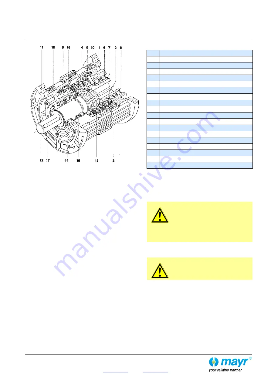
Fig. 1
Parts List
(Only use
mayr
®
original parts)
Item
Name
1
Housing, drive
2
Drive shaft
3
Coil carrier, clutch
4
Automatic re-adjustment
5
Cap screw
6
Deep groove ball bearing
7
Shim rings
8
Locking ring
9
Cap screw
10
Guideline sign, drive
11
Housing, output
12
Output shaft
13
Coil carrier, brake
14
Deep groove ball bearing
15
Radial shaft sealing ring (acc. design)
16
Cap screw
17
Key
18
Guideline sign, output
Design
The ROBA
®
-takt clutch brake unit consists of an 'energise to
engage' clutch and an 'energise to engage' brake. The electrical
connection is produced via a terminal box with a 4-pole terminal.
The clutch brake unit is completely enclosed and complies with
Protection IP55, the dimensions of the flanges and shafts
correspond to the IEC dimensions.
Due to the patented principle of automatic re-adjustment, the
ROBA
®
-takt clutch brake unit is maintenance-free for the entire
service lifetime of the clutch and brake.
The clutch brake units are delivered manufacturer-assembled
and set ready for installation.
Function
On continuously running drive machines, the output is coupled
and braked alternately.
Coupling:
The magnetic coil in the clutch is energised, the magnetic coil in
the brake must be voltage-free.
The rotating drive shaft (2) attracts the armature disk. The torque
is transmitted via frictional locking from the drive shaft (2) via the
armature disk onto the output shaft (12).
Braking:
The brake coil is energised, the clutch coil must be voltage-free.
The armature disk is attracted by the fixed brake coil carrier (13).
The output shaft (12), which is connected with the armature disk
via disks, is braked.
The drive shaft (2) runs continuously.
Ambient Conditions
ROBA
®
-takt clutch brake units are designed for dry running.
Ambient temperature: -20 °C up to +40 °C
CAUTION
At temperatures of around or under freezing
point (ambient temperatures of -20 °C up to
+5 °C), both condensation and the special
characteristics of the linings (lower friction
values at lower temperatures) can strongly
reduce the torque. During longer downtimes,
the friction linings can stick to the friction
surfaces. The user is responsible for taking
appropriate countermeasures.
An ambient temperature of +40 °C should not be exceeded if the
device is run with friction work values in the area of the max.
permitted values.
CAUTION
Higher temperatures lead to unpermittedly
strong heat-up with friction work values in the
limit area.
Torque
The torque (catalogue value) is not achieved until after the run-in
procedure has been carried out.
Normally, this requires approx. 100 switching actions in dynamic
operation. In new condition, approx. 50 % of the torque (M
2
)
stated in the catalogue is transmitted. Clutch brake units in static
or virtually static operation (i.e. low friction work) do not transmit
the full torque (M
2
) stated in the catalogue.