


Installation and Operational Instructions for
EAS
®
-smartic
®
s
ynchronous clutch Type 48_._ _5._
Sizes 01
– 2
(B.4.17.1.GB)
25/11/2011 TK/NU/SU
Chr. Mayr GmbH + Co. KG
Tel.: +49 8341 804-0
Eichenstraße 1
Fax: +49 8341 804-421
D-87665 Mauerstetten
http://www.mayr.com
Page 7 of 18
Germany
E-Mail:
Design
The EAS
®
-smartic
®
clutch is designed as a mechanical
disengaging overload clutch according to the ball detent
principle.
State of Delivery
The EAS
®
-smartic
®
clutch is manufacturer-assembled ready for
installation.
If no particular torque adjustment is requested customer-side,
the EAS
®
-smartic
®
clutch will always be pre-set to approximately
80 % of the maximum torque.
The reference marking on the adjusting nut (5) or on the locking
ring (21) and the torque specification on the Adjustment Table
(11) directly show the set value.
The hexagon head screw (6/22) is not secured with Loctite on a
pre-set clutch.
Before initial operation of the clutch, please secure the locking
screw (6/22) with Loctite 243.
Please check the state of delivery immediately according to the
Parts List!
mayr
®
will take no responsibility for belated complaints.
Please report transport damage immediately to the deliverer.
Please report incomplete delivery and obvious defects to the
manufacturer.
Function
Function in Normal Operation
The EAS
®
-smartic
®
clutch Type 481. transmits the torque from
the input shaft onto the output element, which can be mounted
onto the ball bearing supported pressure flange (3) of the clutch.
The torque is transmitted backlash-free over the entire service
lifetime of the clutch.
The EAS
®
-smartic
®
Types 484. and 486. connect two shafts and
compensate for shaft misalignments.
Function on Overload
If the set limit torque is exceeded, the clutch disengages. The
torque drops immediately.
The residual torque is approx. 5 - 20 % of the set torque (at
approx. 1500 rpm).
Therefore, the EAS
®
-smartic
®
clutch is not load-holding.
An installed limit switch (Item 18 / not included in delivery)
registers the disengagement movement and switches off the
drive.
Once the cause of malfunction has been removed, the clutch is
automatically ready for operation after having reached the
synchronous position:
Re-engagement after 360°.
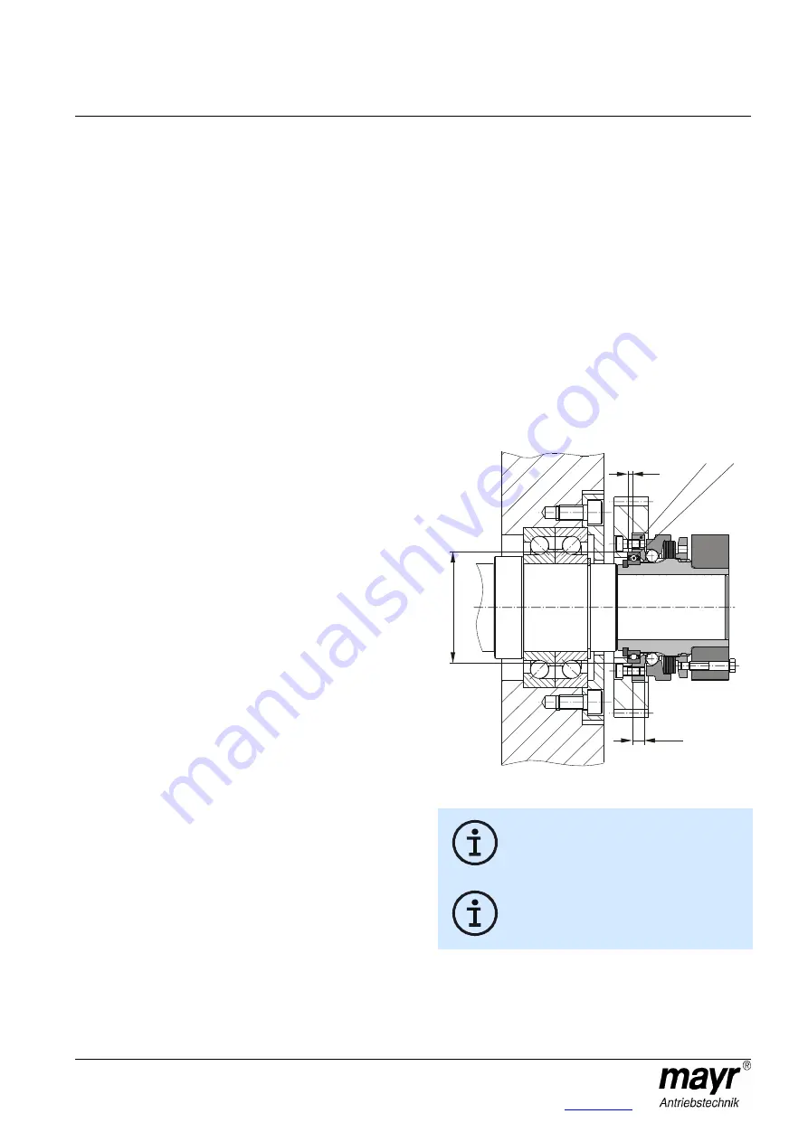
Installation of the Output Elements (Fig. 4)
The output elements are centred on the deep groove ball
bearing (7) (tolerance H7/h5) and screwed together with the
pressure flange (3).
Please use
screws with a strength class of 12.9
with the
corresponding tightening torques acc. Table 1 (tightening
torque Item 14) for screwing onto the pressure flange (3).
The output element must be made of a material with a
minimum tensile strength of approx. 600 N/mm
2
.
Please contact the manufacturers if this is not the case.
If the resulting radial force from the output element is anywhere
near the centre of the ball bearing, an additional bearing for the
output element is not necessary.
No appreciable axial forces should be transmitted from the
output element onto the clutch pressure flange (3).
Output elements with a very small diameter can be screwed
together with the clutch pressure flange (3) via a customer-side
intermediate flange.
Ball bearings, needle bearings or bearing bushings are suitable
as bearings for the output element, depending on the
installation situation and the installation space.
Please make sure that the output element bearing is designed
as a location bearing (Fig. 4).
Fig. 4
The radial forces, axial forces or transverse
force torques, which are introduced into the
clutch bearing must not exceed the permitted
values acc. Table 1.
Please observe the connection dimensions "a"
and "e" for the output elements as well as the
maximum permitted screw-in depth "b
max.
" in
the pressure flange (3); see Fig. 4 and Table 1
on page 5.
7
3
a
Ø
e
b
max.


