Mayr EAS-smartic 481.XX5 Series Installation And Operational Instructions Download Page 12

Installation and Operational Instructions for 
EAS

®

-smartic

®

 s

ynchronous clutch  Type 48_._ _5._ 

Sizes 01 

– 2 

(B.4.17.1.GB)


25/11/2011 TK/NU/SU  

Chr. Mayr GmbH + Co. KG 

Tel.: +49 8341 804-0 


Eichenstraße 1 

Fax: +49 8341 804-421 


D-87665 Mauerstetten 

http://www.mayr.com 

Page 12 of 18 

Germany 

E-Mail: 

[email protected]


Torque Adjustment 

In order to guarantee low-wear clutch operation, it is essential to 
adjust the torque to a sufficiently high service factor (overload 
torque to operating torque). Our experience has shown that an 
adjustment factor of 1,3 to 3 gives good results.  
For very high load changes, high accelerations and uneven 
operation, please set the adjustment factor higher. 

The respective torque adjustment range is printed on the 
Adjustment Table (11). Torque adjustment is carried out by 
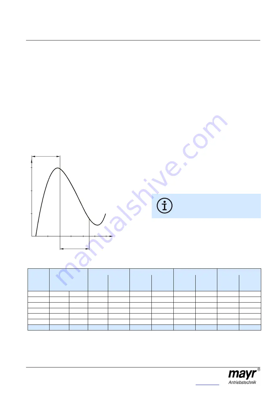
turning the adjusting nut (5/20). The installed cup springs (10) 
are operated in the negative range of the characteristic curve 
(see Fig. 14). This means that tightening the adjusting nut 
(5/20) causes the spring force to decrease, and loosening the 
adjusting nut (5/20) causes the spring force to increase. 
If no torque is specified on order, the clutch is pre-set to 
approx. 80 % of the maximum torque. The reference marking 
and the torque specification show the set value directly.  
If no changes to the pre-set clutch torque are required 
customer-side, the hexagon head screws (6/22) must 
nevertheless be screwed out, painted with Loctite 243 and 
screwed back in again by the customer. 


Fig. 14 


Cup Spring Layering 

Correct cup spring layering is a prerequisite for problem-free 
clutch function and torque adjustment.  
On all Sizes, 7 torque ranges (see Table 3) are possible. 


Changing the Torque 

On clamping ring hub designs 

Type 48_._35._ 


and Type 48_._45._ 

In order to adjust the torque to a different value, simply 

1.  loosen and unscrew the hexagon head screw (6), 

2.  adjust the adjusting nut (5) using a hook wrench until the 

reference marking shows the required torque value, 

3.  if necessary, correct the adjusting nut (5) position slightly 

until the marking notches between the clamping ring hub 
(1/1.1) and the adjusting nut (5) align, and 

4.  paint the hexagon head screw (6) with Loctite 243 before 

screwing it back in again. 
 

On key design Type 48_._25._ 

In order to adjust the torque to a different value, simply 

1.  loosen and unscrew the hexagon head screw (22), 

2.  adjust the adjusting nut (20) using a hook wrench until the 

reference marking shows the required torque value, 

3.  if necessary, correct the adjusting nut (20) position slightly 

until the marking notches between the locking ring (21) and 
the adjusting nut (20) align, and 

4.  paint the hexagon head screw (22) with Loctite 243 before 

screwing it back in again. 


Adjusting the adjusting nut (5/20) or distorting 
the cup springs (10) outside of the cup spring 
characteristic curve (see Fig. 14) stops the 
clutch functioning. 


Table 3: Cup Spring Layering and Torque Ranges 


Size 01 

Size 0 

Size 1 

Size 2 


Type 


Cup spring 

layering 

3)


[Nm] 

Graduation 

lines for 

M = 80 % 


[Nm] 

Graduation 

lines for 

M = 80 % 


[Nm] 

Graduation 

lines for 

M = 80 % 


[Nm] 

Graduation 

lines for 

M = 80 % 

48_.2_5._ 

1x1 times  1 \ /////// 7 

2,7 

– 5 

19 

– 10 

21 

10 

– 20 

16 

20 

– 40 

25 

48_.3_5._ 

1x2 times  2 \\ ////// 6 

– 10 

19 

10 

– 20 

22 

20 

– 40 

17 

40 

– 80 

26 

48_.4_5._ 

1x3 times  3 \\\ ///// 5 

– 15 

20 

15 

– 30 

23 

30 

– 60 

19 

60 

– 120 

28 

48_.5_5._ 

1x4 times  4 \\\\ //// 4 

11 

– 20 

20 

20 

– 40 

23 

40 

– 80 

19 

80 

– 160 

28 

48_.6_5._ 

1x6 times  6 \\\\\\ // 2 

18 

– 33 

20 

35 

– 65 

24 

70 

– 125 

20 

140 

– 250 

30 

48_.7_5._ 

1x8 times  8 \\\\\\\\  0 

32 

– 40 

21 

60 

– 80 

27 

120 

– 160 

25 

240 

– 320 

32 

48_.8_5._

 4)

  1x8 times  8 \\\\\\\\  0 

35 

– 60 

24 

70 

– 120 

31 

150 

– 240 

25 

300 

– 500 

35 

3)

  Example: 

On Type 481.425.0, the cup spring layering is 1x3 times, which means that three cup springs are engaged thrust washer-side  


and five cup springs are not engaged (adjusting nut-side) => 3 \\\ ///// 5. 

4)

  Types 48_.8_5._ require a special pressure flange as well as a special thrust washer. 


Path to

operating range

F

o

rc

e

 F

Graph of 

spring characteristic 

curve

Operating

range

Spring path S

Summary of Contents for EAS-smartic 481.XX5 Series

Page 1: ...ions Breakdowns Type 486 Safety and Guideline Signs CAUTION Danger of injury to personnel and damage to machines Please Observe Guidelines on important points Safety Regulations These Installation and...

Page 2: ...auerstetten http www mayr com Page 2 of 18 Germany E Mail info mayr de Type 481 _ _ _ _ Clamping ring hub with and without keyway Hub key design Fig 1 Type 484 _ _ _ _ Clamping hub Clamping ring hub w...

Page 3: ...Germany E Mail info mayr de Type 486 _ _ _ _ Clamping hub with and without keyway Single jointed Size 2 design Hub key design Size 2 Clamping ring hub with and without keyway Hub large Double jointed...

Page 4: ...er 26 Cap screw 5 Adjusting nut for clamping ring hub design 27 Screw 6 Hexagon head screw for clamping ring hub design 28 Hexagon head screw 7 Deep groove ball bearing 29 Hexagon nut 8 Locking ring 3...

Page 5: ...bore 22 Nm 2 4 1 Tightening torque 37 Nm 8 5 8 5 8 5 Axial forces N 400 500 800 1200 Radial forces N 400 500 800 1200 Transverse force torques 2 Nm 3 5 10 15 Distance dimension E see Figs 5 and 6 mm 1...

Page 6: ...crew M5 x 10 DIN EN ISO 4017 8 8 1x hexagon head screw M5 x 12 DIN EN ISO 4017 8 8 26 Type 486 _ _5 _ 4x cap screw M4 x 16 DIN EN ISO 4762 12 9 8x cap screw M4 x 16 DIN EN ISO 4762 12 9 6x cap screw M...

Page 7: ...mediately The residual torque is approx 5 20 of the set torque at approx 1500 rpm Therefore the EAS smartic clutch is not load holding An installed limit switch Item 18 not included in delivery regist...

Page 8: ...ore installing the clutch Greasy or oily bores or shafts do not transmit the torque TR specified on order Mount the clutch onto the shaft end and bring it into the correct position Tighten the clampin...

Page 9: ...e flexible elastomeric element 15 an axial installation force is required for joining both clutch hubs 1 and 16 The amount of force required can be reduced by lightly greasing the elastomeric element...

Page 10: ...clutch onto the respective shaft and bring it into the correct position Tighten the clamping screw s of the first clutch hub using a torque wrench to the torque stated in Table 1 Mount the second clu...

Page 11: ...to clutch operation at nominal torque an ambient temperature of 30 C and an operating speed of 1500 rpm In other or more extreme clutch operating conditions please contact the manufacturers Radial Ax...

Page 12: ...just the adjusting nut 5 using a hook wrench until the reference marking shows the required torque value 3 if necessary correct the adjusting nut 5 position slightly until the marking notches between...

Page 13: ...the hub 1 5 Change the cup spring layering 10 acc Table 3 6 Screw the adjusting nut 5 clockwise onto the hub 1 up to contact on the cup springs 10 7 Push the clamping ring 1 2 into the correct positio...

Page 14: ...rtic clutches Size 01 we generally recommend the use of smaller contactless limit switches e g M8 x 1 or similar devices Maintenance The EAS smartic clutch is mainly maintenance free The only maintena...

Page 15: ...d Incorrect torque adjustment 1 Set the system out of operation 2 Check whether foreign bodies influence the clutch function 3 Check the torque adjustment 4 Secure the adjusting nut 5 If the cause of...

Page 16: ...Set the system out of operation 2 Check the coupling alignment 3 Tighten the tensioning and clamping screws for axial hub securement as well as connection screws to the required torque or tighten the...

Page 17: ...the alignment and correct if necessary 6 Make sure that further physical changes in the elastomeric element can be excluded The ambient or contact temperatures permitted for the elastomeric element ar...

Page 18: ...rew and secure it against self loosening using sealing lacquer 4 Check the coupling for wear Disk pack breakage Type 486 Disk pack breakage due to high load impacts overload 1 Set the system out of op...

Reviews: