background image

Product Overview

1

Chapter 1: Product Overview

Congratulations on your purchase of this SS-4503E/SS-4503R RAID system. Aiming at serving versatile applications, the 

SS-4503E/SS-4503R RAID system ensures not only data reliability but also improves system availability. Supported with 

cutting-edge IO processing technologies, the RAID system delivers outstanding performance and helps to build 

dependable systems for heavy-duty computing, workgroup file sharing, service-oriented enterprise applications, online 

transaction processing, uncompressed video editing, or digital content provisioning. With its advanced storage 

management capabilities, the RAID system is an excellent choice for both on-line and near-line storage applications. The 

following sections in this chapter will present an overview of the features of SS-4503E/SS-4503R RAID system.

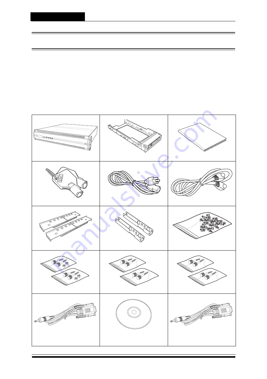
1.1   Package Contents

The following items come with your RAID system package, if any of them is missing or damaged, please contact your 

supplier.

RAID system

Hard disk tray x 12

Quick Install Guide

Front panel key x 2

Power cable x 2

RJ-45 Lan cable

Rail x 1 set

Rail extender x 1 set

Screw pack

M5 fix screw x 2 packs

M6 fix screw x 2 packs

UNC # 10-32 fix screw x 2 packs

Terminal cable 

Phonejack to DB-9(male)

(SS-4503E x1; SS-4503R x2)

CD-ROM

UPS cable x 1

Phonejack to DB-9(Female)

Hardwa

rd User

 Manua

l

Summary of Contents for SS-4503E

Page 1: ...SS 4503E SS 4503R Hardware Manual iSCSI to SAS Disk Array Systems Version 1 0...

Page 2: ......

Page 3: ...SS 4503E SS 4503R iSCSI to SAS Disk Array Systems Hardware User Manual...

Page 4: ......

Page 5: ...ard Disks 7 SAS hard disks 7 SATA hard disks 9 Combining SATA SAS 11 Mounting the RAID system 13 Chapter 3 System Connections 13 Connecting to the Host 13 Connecting the GUI Management Port 13 Connect...

Page 6: ...not installed and used in accordance with the instruction manual may cause harmful interference to radio communications Operation of this equipment in a residential area is likely to cause harmful int...

Page 7: ...quid If the RAID system has been dropped or the casing damaged Never push any kind of object through the slots and openings Slots and opening are for ventilation Never block or cover them Never place...

Page 8: ...tent provisioning With its advanced storage management capabilities the RAID system is an excellent choice for both on line and near line storage applications The following sections in this chapter wi...

Page 9: ...surface capable of supporting the RAID system LAN management port settings SS 4503E SS 4503R support DHCP Dynamic Host Configuration Protocol to establish an IP address To know current IP address by...

Page 10: ...se to move up the LCD menu 6 Down button Use to move down the LCD menu 7 Enter button Use to confirm or select an item 8 Escape button Use to return to the previous LCD menu 9 Lock Locks the front cov...

Page 11: ...or Indicates the disk status Green Disk is online Red No disk or disk fail 2 Tray button Press to release the tray handle 3 Access LED indicator Lights blue when the disk is being accessed 4 Tray hand...

Page 12: ...only 7 UPS port Provides UPS powered data connection 8 Power supply 2 Removable power supply 9 Cooling fan 2 System cooling fan 10 Controller A RAID system controller A Primary controller 11 Expansion...

Page 13: ...roller A Use for JBOD expansion SS 6692R 12 Host channel Controller A Connects to the host server 13 COM port Controller A Connects to external terminal for CLI management 14 Ethernet port Controller...

Page 14: ...into the hard disk tray Screw the sides to secure the hard disk Repeat this procedure to install more hard disks 2 Insert the key to the key slot and turn to unlock the front panel door 3 Pull open t...

Page 15: ...re the hard disk tray into place 6 Repeat steps 4 to 5 until all the required disks have been installed 7 Close the front panel door then lock it Disk1 Disk2 Disk3 Disk4 Disk5 Disk6 Disk7 Disk8 Disk9...

Page 16: ...ent AA MUX tray board is equipped with SATA connector on one end and SAS connector on the other end to enable RAID system connetions Follow the procedures below to install SATA hard disks 1 Place the...

Page 17: ...rd and connect the power and data connectors 4 Attach the screws to secure the hard disk 5 Insert the hard disk tray into an empty slot 6 Push down the tray handle to secure the hard disk tray into pl...

Page 18: ...system When combining SATA and SAS disks in the same enclosure following figures will help you to plan the placement Configuration Set SATA or SAS at the same side Set SATA or SAS at the same column r...

Page 19: ...eight rack nuts into the rack making sure that they correspond with the mounting points on the rails 2 Adjust the length of the rails as needed 3 Secure the rails using two nuts and bolts on both the...

Page 20: ...e chassis at botton side please follow the procedures below to install the rail extenders Follow the procedures below to install the rail extenders 1 Install the rail extenders and attach the screws t...

Page 21: ...6 ethernet cables To connect a cable simply insert the cable to the CH1 port Connect the other end of the cable to the iSCSI HBA connector of the host server or Gigabit ethernet switch 3 2 Connecting...

Page 22: ...he other end to an external terminal 3 4 Connecting JBOD Enclosure Follow the procedures below to connect to external JBOD system SS 6692E SS 6692R 1 Insert a miniSAS connector to the EXP port on the...

Page 23: ...vides SMART UPS management of the UPS via a serial port DB 9 RS232 Two cables were necessary to get it works one UPS cable Phonejack to DB 9 A of accessary package of RAID system the other UPS cable D...

Page 24: ...or 2 Push the button to release the tray handle 3 Grab the handle and gently pull out the disk tray 4 Unscrew the hard disk to detach it from the disk tray 5 Replace with a new hard disk To install th...

Page 25: ...t and serial power cables connected to the faulty controller 2 Loosen the screws of the controller 3 Lift the handle to eject the controller 4 Gently pull out the controller 5 Insert the new controlle...

Page 26: ...entify the faulty power supply 2 Detach the power cable from the power supply 3 Loosen the screws of the faulty power supply 4 To remove the power supply press the release catch and pull the handle at...

Page 27: ...ow the procedures below 1 Loosen the screws of the controller 2 Forcefully lift up the handle to eject the controller then gently pull it out 3 To remove the memory card release the retaining clips to...

Page 28: ...A faulty fan module is indicated with a message on the LCD panel and the audible alert sounds Follow the procedure below to replace the faulty fan module 1 Loosen the screws then pull out the faulty...

Page 29: ...dule A 3 Secure the BBM by fastening 4 screws on the bottom of the Fan module B 4 Connect the small end of the cable to the connector port of the BBM Then connect the other end to the BBM connectot of...

Page 30: ...hysical Dimensions 485 W x 565 D x 88 H mm Physical Weight 19 kgs without drives Packed Dimensions 610 W x 790 D x 430 H mm Packed Weight 28 kgs without drives Certifications Safety Regulatory UL CUL...

Page 31: ...s The following lists other components and accessories that can be used with the RAID system and are purchased separetely SAS JBOD SS 6692E SS 6692R SS 8892E SS 8892R AA MUX tray board for SATA Hard D...

Reviews: