


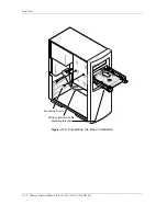


Installation
Maxtor DiamondMax Plus9 60/80/120/160/200GB AT
3-15
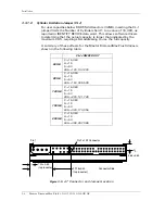
The following points should be noted:
All pins are in a single row, with a 1.27 mm (.050”) pitch.
• The comments on the mating sequence in Table 3-3 apply to
the case of backplane blindmate connector only. In this case,
the mating sequences are: (1) the ground pins P4 and P12; (2)
the pre-charge power pins and the other ground pins; and (3)
the signal pins and the rest of the power pins.
• There are three power pins for each voltage. One pin from
each voltage is used for precharge in the backplane blind-mate
situation.
• If a device uses 3.3 V, then all V
33
pins must be terminated.
Otherwise, it is optional to terminate any of the V
33
pins. If a
device uses 5.0 V, then all V
5
pins must be terminated.
Otherwise, it is optional to terminate any of the V
5
pins.
• If a device uses 12.0 V, then all V
12
pins must be terminated.
Otherwise, it is optional to terminate any of the V
12
pins.
3.5.1
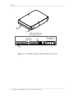
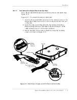
ATA Bus Interface Connector (J1, Section C)
On the Maxtor DiamondMax Plus9 60/80/120/160/200GB AT hard disk
drives, the SATA bus interface cable connector (J1, section C) is a
standard 7-pin SATA.
To prevent the possibility of incorrect installation, the connector has
been keyed. This ensures that a connector cannot be installed upside
down.MOUNTING
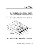
Drive mounting orientation, clearance, and ventilation requirements are
described in the following subsections.
3.5.2
Orientation
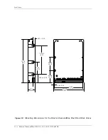
The mounting holes on the Maxtor DiamondMax Plus9 60/80/120/160/
200GB AT hard disk drives allow the drive to be mounted in any
orientation. Figure 3-5 and Figure 3-9 show the location of the three
mounting holes on each side of the drive. The drive can also be mounted
using the four mounting hole locations on the PCB side of the drive.
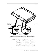
Note: It is highly recommended that the drive is hard mounted
on to the chassis of the system being used for general
operation, as well as for test purposes. Failure to hard
mount the drive can result in erroneous errors during
testing.
Drives can be mounted in any orientation. Normal posi-
tion is with the PCB facing down.
All dimensions are in millimeters. For mounting, #6-32 UNC screws are
recommended.