background image

©

 October 30, 2003 Maxtor Corporation. All rights reserved. Printed in U.S.A.

This publication could include technical inaccuracies or typographical errors. Changes are 
periodically made to the information herein – which will be incorporated in revised editions 
of the publication. Maxtor may make changes or improvements in the product(s) described 
in this publication at any time and without notice.

UL/CSA/VDE/TUV 

UL standard 1954 recognition granted under File No. E78016

CSA standard C22.2-950 certification granted under File No. LR49896

TUV Rheinland EN 60 950

Tested to FCC Rules for Radiated and Conducted Emissions, Part 15, Sub Part J, for Class-
B Equipment.

PATENTS

These products are covered by or licensed under one or more of the following U.S. Patents:


4,419,701; 4, 538,193 4,625,109; 4,639,798; 4,647,769; 4,647,997; 4,661,696; 
4,669,004; 4,675,652; 4,703,176; 4,730,321; 4,772,974; 4,783,705; 4,819,153; 
4,882,671; 4,920,442; 4,920,434; 4,982,296; 5,005,089; 5,027,241; 5,031,061; 
5,084,791; 5,119,254; 5,160,865; 5,170,229; 5,177,771; Other U.S. and Foreign Pat-
ents Pending.

Maxtor

®

, MaxFax

®

 are registered trademarks of Maxtor Corporation, registered in the U.S.A. 

and other countries. Maxtor DiamondMax Plus9, AutoTransfer, AutoRead, AutoWrite, Dis-
Cache, DiskWare, Defect Free Interface, and WriteCache are trademarks of Maxtor Corpora-
tion. All other brand names or trademarks are the property of their manufacturers.

Maxtor reserves the right to make changes and improvements to its products, without 
incurring any obligation to incorporate such changes or improvements into units previously 

Summary of Contents for DiamondMax Plus9 120GB AT

Page 1: ...DiamondMax Plus9 60 80 120 160 200GB AT Product Manual October 30 2003 Part Number 1877 ...

Page 2: ...are covered by or licensed under one or more of the following U S Patents 4 419 701 4 538 193 4 625 109 4 639 798 4 647 769 4 647 997 4 661 696 4 669 004 4 675 652 4 703 176 4 730 321 4 772 974 4 783 705 4 819 153 4 882 671 4 920 442 4 920 434 4 982 296 5 005 089 5 027 241 5 031 061 5 084 791 5 119 254 5 160 865 5 170 229 5 177 771 Other U S and Foreign Pat ents Pending Maxtor MaxFax are registere...

Page 3: ...ctions as set forth in subparagraphs c 1 ii of the Rights in Technical Data and Computer Software clause at DFARS 252 227 7013 and FAR 52 227 19 THIS PUBLICATION IS PROVIDED AS IS WITHOUT WARRANTY OF ANY KIND EITHER EXPRESS OR IMPLIED INCLUDING BUT NOT LIMITED TO THE IMPLIED WARRANTIES OF MERCHANTABILITY FITNESS FOR A PARTIULAR PURPOSE OR NON INFRINGEMENT You can request Maxtor publications from y...

Page 4: ... Maxtor shipping container IMMEDIATELY secure the drive through its mounting holes within a chassis Otherwise store the drive on a padded grounded antistatic surface 5 NEVER switch DC power onto the drive by plugging an electrically live DC source cable into the drive s connector NEVER connect a live bus to the drive s inter face connector 6 ELECTRICAL GROUNDING For proper operation the drive must...

Page 5: ... 1 3 2 UNPACKING INSTRUCTIONS 3 2 3 3 HARDWARE OPTIONS 3 5 3 3 1 ATA Interface Connector 3 5 3 3 2 ATA BUS ADAPTER 3 9 3 4 COMBINATION CONNECTOR J1 3 9 3 4 1 DC Power J1 Section A 3 11 3 4 2 External Drive Activity LED 3 11 3 4 3 ATA Bus Interface Connector J1 Section C 3 11 3 4 4 SATA Serial ATA Interface Connector 3 12 3 4 5 SATA BUS ADAPTER 3 12 3 5 COMBINATION CONNECTOR J1 3 13 3 5 1 DC Power ...

Page 6: ... 1Power Requirement 200GB 4 3 4 6 Power Mode Definitions 4 4 4 7 EPA Energy Star Compliance 4 4 4 8 Environmental Limits 4 5 4 9 Shock and Vibration 4 6 4 10 Reliability Specifications 4 7 4 11 EMC EMI 4 8 4 11 1 Radiated Electromagnetic Field Emissions EMC Compliance 4 8 4 11 2 Canadian Emissions Statement 4 8 4 12 Safety Regulatory Compliance 4 8 Chapter 5 ATA BUS INTERFACE AND ATA COMMANDS 5 1 ...

Page 7: ...BYTE STORAGE BARRIER 1 A 1 Breaking the 137 Gigabyte Storage Barrier A 1 A 1 1 History A 1 A 1 2 Solving the 137 Gigabyte Capacity Barrier A 3 A 1 3 How is the Extension Implemented A 3 A 1 4 What Do the Drives Need to Meet the Spec A 3 A 1 5 What Else is Involved A 3 A 1 6 What is the Next Barrier A 4 ...

Page 8: ...face Connector 3 5 Figure 3 5 AT Connector and Jumper Location 3 8 Figure 3 6 J1 DC Power and ATA Bus Combination Connector 3 10 Figure 3 7 The SATA Interface Connector 3 12 Figure 3 8 Serial ATA PCB 3 13 Figure 3 9 Mounting Dimensions for the Maxtor DiamondMax Plus9 Hard Disk Drives 3 17 Figure 3 10 Mounting Screw Clearance for the Maxtor Hard Disk Drives 3 18 Figure 3 11 Drive Power Supply and A...

Page 9: ...umper Options 3 6 Table 3 2 J1 Power Connector Section A 3 11 Table 3 3 J1 Power Connector Section A 3 14 Table 3 4 Device plug connector pin definition 3 15 Table 3 5 Logical Addressing Format 3 25 Table 5 1 Supported Commands 5 2 Table 5 2 Identify Drive Command Parameters 5 5 ...

Page 10: ... information to help resolve any difficulties These options include a broad searchable knowledge base of FAQ s product manuals installation guides information on previously resolved problems software downloads and contact by phone or E mail with a support person For more information visit www maxtor com en support 1 2 Audience The DiamondMax Plus 9 60 80 120 160 200GB AT product manual is intended...

Page 11: ... 4 TERMINOLOGY AND CONVENTIONS In the Glossary at the back of this manual you can find definitions for many of the terms used in this manual In addition the following abbreviations are used in this manual ASIC application specific integrated circuit ATA advanced technology attachment bpi bits per inch DA Double Amplitude represents pk pk shaker displacement dB decibels dBA decibels A weighted DPS ...

Page 12: ...mes of Bits Bit names are presented in initial capitals An example is the Host Software Reset bit Commands Interface commands are listed in all capitals An example is WRITE LONG Register Names Registers are given in this manual with initial capitals An example is the Alternate Status Register Parameters Parameters are given as initial capitals when spelled out and are given as all capitals when ab...

Page 13: ...oice This refers to items you type at the computer keyboard These items are listed in 10 point all capitals Courier font An example is FORMAT C S 1 5 REFERENCES For additional information about the ATA interface refer to the latest revision of the draft standard on the internet at http www t13 org using the link under 1410D AT Attachment 6 with Packet Interface ATA ATAPI 6 ...

Page 14: ... use ATA commands to optimize system performance Because the drive manages media defects and error recovery internally these operations are fully transparent to the user The innovative design of the Maxtor DiamondMax Plus9 hard disk drives incorporate leading edge technologies such as Ultra ATA 133 Serial ATA Option with transfer speeds up to 150 MB second Advanced Cache Management Shock Protectio...

Page 15: ...d double burst ECC on the fly 1 1 interleave on read write operations Support of all standard ATA data transfer modes with PIO mode 4 and multiword DMA mode 2 and Ultra DMA modes 0 1 2 3 4 5 and 6 Adaptive cache segmentation 100 FDB Fluid Dynamic Bearing Motors Reliability Automatic retry on read errors 320 bit non interleaved Reed Solomon Error Correcting Code ECC with cross checking correction u...

Page 16: ...ry certification pertaining to all 3 5 inch series drives models Product EMI EMS Qualifications CE Mark authorization is granted by TUV Rheinland in compliance with our qualifying under EN 55022 1994 and EN 50082 1 1997 C Tick Mark is an Australian authorization marked noted on Maxtor s disk drive products The mark proves conformity to the regulatory compliance document AS NZS 3548 1995 and BS EN ...

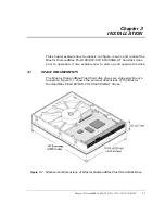
Page 17: ...60 200GB AT hard disk drive prior to operation It also explains how to start up and operate the drive 3 1 SPACE REQUIREMENTS The Maxtor DiamondMax Plus9 hard disk drives are shipped without a faceplate Figure 3 1 shows the external dimensions of the Maxtor DiamondMax Plus9 60 80 120 160 200GB AT drives Figure 3 1 Mechanical Dimensions of Maxtor DiamondMax Plus9 Hard Disk Drive ...

Page 18: ... handled properly Special care should be taken not to bump or drop the drive It is highly recommended that Maxtor DiamondMax Plus9 drives are not stacked or placed on any hard surface after they are unpacked Such handling could cause media damage CAUTION During shipment and handling the antistatic electrostatic dis charge ESD bag prevents electronic component damage due to electrostatic discharge ...

Page 19: ...0 160 200GB AT 3 3 Figure 3 2 shows the shipping container for a single Maxtor DiamondMax Plus9 hard disk drive Figure 3 3 shows the shipping container for a 20 pack of Maxtor DiamondMax Plus 9 hard drives Figure 3 2 Single Pack Shipping Container ...

Page 20: ...llation 3 4 Maxtor DiamondMax Plus9 60 80 120 160 200GB AT Figure 3 3 20 Pack Shipping Container 20 pack cover 20 pack tray Product in sealed static shielding bag BC label facing up Sleeve Carton Carton tape ...

Page 21: ...stalled This section describes the hardware options that you must take into account prior to installation Figure 3 4 Jumper Locations on the ATA Interface Connector Pin 40 ATA Interface Connector Power Connector Pin 1 12VDC 5VDC return 12VDC return 5VDC DS CS CLJ DS CS CLJ DS CS CLJ DS CS CLJ Cable Select Setting default Master Setting Slave Setting DS with CS for slaves not supporting DASP Note t...

Page 22: ... not matter 3 3 1 1 Cable Select CS Jumper When a Maxtor DiamondMax Plus9 60 80 120 160 200GB AT hard disk drive and another ATA hard disk drive are daisy chained together they can be configured as Master or Slave either by the CS or DS jumpers To configure the drive as a Master or Slave with the CS feature the CS jumper is installed 1 The drive s position on the 80 conductor Ultra ATA data cable ...

Page 23: ...e as a Slave Device 1 DS scheme the CS jumper must be removed In this configuration the spare jumper removed from the CS position may be stored on the PK jumper pins 3 3 1 2 Drive Select DS Jumper You can also daisy chain two drives on the ATA bus interface by using their Drive Select DS jumpers To use the DS feature the CS jumper must not be installed To configure a drive as the Master Device 0 a...

Page 24: ...ger than indicated by the maximum CHS requiring LBA addressing to use the full capacity A summary of these effects for the Maxtor DiamondMax Plus9 drives is shown in the following table Figure 3 5 AT Connector and Jumper Location CLJ JUMPER OUT 60GB C 16 383 H 16 S 63 LBA 120 103 200 80GB C 16 383 H 16 S 63 LBA 160 086 528 120GB C 16 383 H 16 S 63 LBA 240 121 728 160GB C 16 383 H 16 S 63 LBA 320 1...

Page 25: ...ly connect a 40 pin ribbon cable between the drive and the motherboard You should also refer to the motherboard instruction manual to ensure signal compatibility 3 3 2 2 Adapter Board If your PC motherboard does not contain a built in 40 pin ATA bus interface connector you must install an ATA bus adapter board and connecting cable to allow the drive to interface with the motherboard Maxtor does su...

Page 26: ...ndMax Plus9 60 80 120 160 200GB AT Figure 3 6 J1 DC Power and ATA Bus Combination Connector J1 IDE 40 Pin DC 4 Pin Combination Connector Pin 1 Center Key Slot 4 3 2 1 4 Pin DC Power J1 Section A 40 Pin IDE J1 Section C Pin 1 Pin 40 ...

Page 27: ...he Maxtor DiamondMax Plus9 60 80 120 160 200GB AT hard disk drives the ATA bus interface cable connector J1 section C is a 40 pin Universal Header as shown in Figure 3 6 To prevent the possibility of incorrect installation the connector has been keyed by removing Pin 20 This ensures that a connector cannot be installed upside down See Chapter 5 ATA Bus Interface and ATA Commands for more detailed ...

Page 28: ...l configurations are controlled in the SATA interface by the host Figure 3 7 The SATA Interface Connector 3 4 5 SATA BUS ADAPTER There are two ways you can configure a system to allow the Maxtor DiamondMax Plus9 hard disk drives to communicate over the SATA bus of an IBM or IBM compatible PC 1 Connect the drive to a SATA bus connector if available on the motherboard of the PC 2 Install an IDE comp...

Page 29: ...ith the motherboard Maxtor does not supply such an adapter board but they are available from several third party vendors Please carefully read the instruction manual that comes with your adapter board to ensure signal compatibility between the adapter board and the drive Also make sure that the adapter board jumper settings are appropriate 3 5 COMBINATION CONNECTOR J1 J1 is a three in one combinat...

Page 30: ...wer segment P1 V33 3 3V power P2 V33 3 3V power P3 V33 3 3V power pre charge 2nd mate P4 Ground 1st mate P5 Ground 2nd mate P6 Ground 2nd mate P7 V5 5V power pre charge 2nd mate P8 V5 5V power P9 V5 5V power P10 Ground 2nd mate P11 Reserved 1 The pin corresponding to P11 in the backplane receptacle connector is also reserved 2 The corresponding pin to be mated with P11 in the power cable receptacl...

Page 31: ... C On the Maxtor DiamondMax Plus9 60 80 120 160 200GB AT hard disk drives the SATA bus interface cable connector J1 section C is a standard 7 pin SATA To prevent the possibility of incorrect installation the connector has been keyed This ensures that a connector cannot be installed upside down MOUNTING Drive mounting orientation clearance and ventilation requirements are described in the following...

Page 32: ...dMax Plus9 60 80 120 160 200GB AT Figure 3 9 Mounting Dimensions for the Maxtor DiamondMax Plus9 Hard Disk Drives 147 0 Max 44 45 0 25 41 28 0 50 95 25 0 25 101 60 0 25 41 60 0 25 101 60 0 25 26 10 Max 6 35 0 25 28 50 0 50 3 18 0 25 ...

Page 33: ...s very close to the mounting holes Do not ex ceed the specified length for the mounting screws The specified screw length allows full use of the mounting hole threads while avoiding damaging or placing unwanted stress on the PCB Figure 3 10 specifies the minimum clearance be tween the PCB and the screws in the mounting holes To avoid stripping the mounting hole threads the maximum torque applied t...

Page 34: ... use a SATA cable 1 meter long or shorter Ensure that pin 1 of the drive is connected to pin 1 of the motherboard connector 3 6 FOR SYSTEMS WITH AN ATA ADAPTER BOARD To install the Maxtor DiamondMax Plus9 60 80 120 160 200GB AT hard disk drive in an AT compatible system without a 40 pin ATA bus connector SATA connector on its motherboard you need a third party IDE compatible adapter board 3 6 1 Ad...

Page 35: ... sure that pin 1 of the connector matches with pin 1 on the cable 2 Insert the other end of the cable into the header on the drive When inserting this end of the cable make sure that pin 1 of the cable connects to pin 1 of the drive connector 3 Secure the drive to the system chassis by using the mounting screws as shown in Figure 3 12 Figure 3 11 Drive Power Supply and ATA Bus Interface Cables Key...

Page 36: ...Installation 3 20 Maxtor DiamondMax Plus9 60 80 120 160 200GB AT Figure 3 12 Completing the Drive Installation Mounting Screws Mounting Bracket ATA Bus Interface Cable ...

Page 37: ...e a hard disk controller that translates the hard drive parameters to an appropriate setup for both MS DOS and the computer system s ROM BIOS Insert the Cylinder Limitation Jumper CLJ on the drive see Section 3 3 1 4 3 7 2 The 8 4 Gigabytes Barrier Newer BIOS s allow users to configure disk drives to go beyond the 528MB barrier by using several BIOS translation schemes However while using these tr...

Page 38: ...ize of 16 bits which will only support partitions up to 2 1 GB Windows 95 OSR2 Windows 98 and Windows ME use a FAT size of 32 bits allowing partitions of up to 2 2 terrabytes Windows NT 2000 and XP Use NTFS which allows partition sizes up to 16 terrabytes 3 8 SYSTEM STARTUP AND OPERATION Once you have installed the Maxtor DiamondMax Plus9 60 80 120 160 200GB AT hard disk drive and adapter board if...

Page 39: ...n of its physical drive geometry parameters such as cylinders heads and sectors per track to a logical addressing mode The drive can work with different BIOS drive type tables of the various host systems You can choose any drive type that does not exceed the capacity of the drive Table 3 4 gives the logical parameters that provide the maximum capacity on the Maxtor DiamondMax Plus9 family of hard ...

Page 40: ... 16 63 120 103 200 60GB 6Y080L0 ATA 133 2 MB Buffer 158 816 16 63 160 086 528 80GB 6Y080P0 8 MB Buffer 158 816 16 63 160 086 528 80GB 6Y080M0 SATA 150 8 MB Buffer 158 816 16 63 160 086 528 80GB 6Y120L0 ATA 133 2 MB Buffer 238 216 16 63 240 121 728 120GB 6Y120P0 8 MB Buffer 238 216 16 63 240 121 728 120GB 6Y120M0 SATA 150 8 MB Buffer 238 216 16 63 240 121 728 120GB 6Y160L0 ATA 133 2 MB Buffer 317 6...

Page 41: ...mber of cylinders heads and sectors for a particular drive type You must choose a drive type that meets the following requirements For the Maxtor DiamondMax Plus9 60 80 120 160 200GB ATGB Logical Cylinders x Logical Heads x Logical Sectors Track x 512 8 455 200 768 4 Boot the system using the operating system installation disk for example MS DOS then follow the installation instructions in the ope...

Page 42: ...eans 1 billion bytes Total accessible capacity varies depending on operating environment MODELS 60GB 80GB 120GB 160GB 200GB Sectors per Drive max LBA 120 103 200 160 086 528 240 121 728 320 173 056 398 297 088 Integrated Interface Maxtor Ultra ATA 133 ATA 5 ATA 6 Maxtor Ultra ATA 133 ATA 5 ATA 6 SATA 150 MB 8 MB Buffer Recording Method RLL EEPR4 Servo Type Embedded Number of Servo Sectors 192 Data...

Page 43: ...eek 20 0 Average Latency ms 4 18 Controller Overhead ms 0 3 Rotation Speed RPM 0 1 7200 Data Transfer Speed MByte sec max To From Interface Maxtor Ultra ATA 133 up to 133 To From Interface SATA with 8 MB Buffer 150 To From Media ID OD up to nn n where nn n is the maximum transfer rate possible ID 460 OD 803 Sustained ID OD up to nn n where nn n is the maximum transfer rate possible ID 37 OD 67 Dat...

Page 44: ...0 Width typical mm 101 6 Depth maximum in mm 147 Weight maximum in grams 630 MODE 12V MA 5V MA POWER W Spin up peak 1509 3 853 2 22 4 Seek 602 8 816 5 11 3 Read Write 410 8 669 9 8 3 Idle 322 6 650 4 7 1 Standby 36 6 123 9 1 1 Sleep 36 9 122 7 1 1 MODE 12V MA 5V MA POWER W Spin up peak 1566 2 841 6 23 2 Seek 666 4 931 3 12 6 Read Write 556 4 665 1 9 5 Idle 456 3 670 8 8 8 Standby 37 2 119 7 1 0 Sl...

Page 45: ...drive is capable of responding to read commands within 40 ms Standby The motor is not spinning The drive will leave this mode upon receipt of a command that requires disk access The time out value for this mode is programmable The buffer is active to accept write data Sleep This is the lowest power state with the interface set to inactive A software or hardware reset is required to return the driv...

Page 46: ...SMART specification and or atmospheric conditions PARAMETER OPERATING NON OPERATING STORAGE Temperature 5 C to 55 C with no ARR impact 0 C to 60 C Margin Demonstrated1 low temperature 40 C high temperature 71 C per MIL STD 810E method 501 3 climatic category hot induced conditions Thermal Gradient 25 C per hour maximum Relative Humidity 5 to 95 non condensing Wet Bulb 30 C maximum Altitude relativ...

Page 47: ...put Rotational Random Vibration 5 2000 Hz 3 60 rad sec2 RMS Overall 2 300 Hz 96 5 rad sec2 RMS Random Vibration 5 2000 Hz 0 44 GRMS Overall PSD 7 800 Hz at 3 08 GRMS No Damage Swept Sine Vibration 1 octave minute peak amplitude 10 to 300 Hz 301 to 400 Hz 401 to 500 Hz 1 0 G 0 to peak amplitude 1 octave per minute 0 25 G 0 to peak amplitude 1 octave per minute 0 0625 G 0 to peak amplitude 1 octave ...

Page 48: ...e failure rate or b the time period up to the wear out point when useful component life expires 4 11 EMC EMI 4 11 1 Radiated Electromagnetic Field Emissions EMC Compliance The hard disk drive mechanism is designed as a subassembly for installation into a suitable enclosure and is therefore not subject to Subpart J of Part 15 of FCC Rules 47CFR15 or the Canadian Department of Communications Radio I...

Page 49: ...unications Le present appareil numerique n emet pas de bruit radioelectriques depassant les limites applicables aux appareils numeriques de Class B prescrites dans le reglement sur le brouillage radioelectrique edicte pa le ministere des communications du Canada 4 12 Safety Regulatory Compliance All Maxtor hard drives comply with relevant product safety standards such as CE CUL TUV and UL rules an...

Page 50: ...guration jumpers The dimensions and specifications of the unitized connector comply with Annex A in the ATA ATAPI standard The Maxtor DiamondMax Plus9 drives require the use of an 80 conductor cable ATA ATAPI 6 Annex A Figure A 4 and description to support the drive s Ultra DMA capability 5 3 ELECTRICAL INTERFACE 5 3 1 ATA Bus Interface 5 3 1 1 Electrical Characteristics Signals on the ATA interfa...

Page 51: ...contained in a proprietary ASIC developed by Maxtor 5 5 2 Supported Commands The Maxtor DiamondMax Plus9 hard disk drives support all the mandatory commands from the general feature set for devices not supporting the Packet command feature set Refer to the ATA ATAPI 6 standard for a detailed description of these commands The IDENTIFY DRIVE command however is elaborated in the section Identify Driv...

Page 52: ... READ VERIFY SECTOR S 40h 41h SECURITY DISABLE PASSWORD F6h SECURITY ERASE PREPARE F3h SECURITY ERASE UNIT F4h SECURITY FREEZE LOCK F5H SECURITY SET PASSWORD F1h SECURITY UNLOCK F2h SEEK 70h SET FEATURES EFh Note 1 SET MAX ADDRESS F9h 00h SET MAX SET PASSWORD F9h 01h SET MAX LOCK F9h 02h SET MAX UNLOCK F9h 03h SET MAX FREEZE LOCK F9h 04h SET MULTIPLE MODE C6h SLEEP 99h E6h Table 5 1 Supported Comm...

Page 53: ... ATTRIBUTE AUTOSAVE B0h D2h SMART EXECUTE OFF LINE IMMEDIATE B0h D4h SMART READ DATA B0h D0h SMART READ LOG B0h D5h SMART RETURN STATUS B0h DAh SMART SAVE ATTRIBUTE VALUES B0h D3h SMART WRITE LOG B0h D6h STANDBY 96h E2h STANDBY IMMEDIATE 94h E0h WRITE BUFFER E8h WRITE DMA CAh CBh WRITE MULTIPLE C5h WRITE PIO OVERLAP 34h WRITE SECTOR S 30h 31h Table 5 1 Supported Commands Command Command Code Featu...

Page 54: ...he host may then read the information out of the sector buffer Parameter words in the buffer are shown in Table 5 2 Note All reserved bits or words should be zeroes Table 5 2 Identify Drive Command Parameters Word CONTENT DESCRIPTION 0 General configuration bit significant information 15 0 ATA device 14 8 Retired 7 1 removable media device 6 Obsolete 5 3 Retired 2 Response incomplete 1 Retired 0 R...

Page 55: ...14 Reserved for the IDENTIFY PACKET DEVICE command 13 1 Standby timer values as specified in this standard are supported 0 Standby timer values shall be managed by the device 12 Reserved for the IDENTIFY PACKET DEVICE command 11 1 IORDY supported 0 IORDY may be supported 10 1 IORDY may be disabled 9 1 LBA supported 8 1 DMA supported 7 0 Retired 50 Capabilities 15 Shall be cleared to zero 14 Shall ...

Page 56: ...dressable sectors 62 Obsolete 63 15 11 Reserved 10 1 Multiword DMA mode 2 is selected 0 Multiword DMA mode 2 is not selected 9 1 Multiword DMA mode 1 is selected 0 Multiword DMA mode 1 is not selected 8 1 Multiword DMA mode 0 is selected 0 Multiword DMA mode 0 is not selected 7 3 Reserved 2 1 Multiword DMA mode 2 and below are supported 1 1 Multiword DMA mode 1 and below are supported 0 1 Multiwor...

Page 57: ...epth 15 5 Reserved 4 0 Maximum queue depth 1 76 79 Reserved for Serial ATA 80 Major version number 0000h or FFFFh device does not report version 15 Reserved 14 Reserved for ATA ATAPI 14 13 Reserved for ATA ATAPI 13 12 Reserved for ATA ATAPI 12 11 Reserved for ATA ATAPI 11 10 Reserved for ATA ATAPI 10 9 Reserved for ATA ATAPI 9 8 Reserved for ATA ATAPI 8 7 Reserved for ATA ATAPI 7 6 1 supports ATA ...

Page 58: ...supported 5 1 write cache supported 4 Shall be cleared to zero to indicate that the PACKET Command feature set is not supported 3 1 mandatory Power Management feature set supported 2 1 Removable Media feature set supported 1 1 Security Mode feature set supported 0 1 SMART feature set supported 83 Command sets supported 15 Shall be cleared to zero 14 Shall be set to on 13 1 FLUSH CACHE EXT command ...

Page 59: ...cleared to zero 14 Shall be set to one 13 8 Reserved 7 1 WRITE DMA QUEUED FUA EXT command supported 6 1 WRITE DMA FUA EXT and WRITE MULTIPLE FUA EXT commands supported 5 1 General Purpose Logging feature set supported 4 1 Streaming feature set supported 3 1 Media Card Pass Through Command feature set supported 2 1 Media serial number supported 1 1 SMART self test supported 0 1 SMART error logging ...

Page 60: ...pported 10 1 48 bit Address features set supported 9 1 Automatic Acoustic Management feature set enabled 8 1 SET MAX security extension enabled by SET MAX SET PASSWORD 7 See Address Offset Reserved Area Boot INCITS TR27 2001 6 1 SET FEATURES subcommand required to spin up after power up 5 1 Power Up In Standby feature set enabled 4 1 Removable Media Status Notification feature set enabled 3 1 Adva...

Page 61: ...1 Ultra DMA mode 3 is selected 0 Ultra DMA mode 3 is not selected 10 1 Ultra DMA mode 2 is selected 0 Ultra DMA mode 2 is not selected 9 1 Ultra DMA mode 1 is selected 0 Ultra DMA mode 1 is not selected 8 1 Ultra DMA mode 0 is selected 0 Ultra DMA mode 0 is not selected 7 Reserved 6 1 Ultra DMA mode 6 and below are supported 5 1 Ultra DMA mode 5 and below are supported 4 1 Ultra DMA mode 4 and bel...

Page 62: ...nal was used 11 some other method was used or the method is unknown 8 Shall be set to one 7 0 Device 0 hardware reset result Device 1 shall clear these bits to zero Device shall set these bits as follows 7 Reserved 6 0 Device 0 does not respond when Device 1 is selected 1 Device 0 responds when Device 1 is selected 5 0 Device 0 did not detect the assertion of DASP 1 Device 0 detected the assertion...

Page 63: ...O 105 Stream Access Latency PIO 106 Physical sector size 15 Shall be cleared to zero 14 Shall be set to one 13 1 Device has multiple logical sectors per physical sector 12 4 Reserved 3 0 2X logical sectors per physical sector 107 Inter seek delay for ISO 7779 acoustic testing in microseconds 108 126 Reserved 127 Removable Media Status Notification feature set support 15 2 Reserved 1 0 00 Removable...

Page 64: ...l 0 High 1 Maximum 7 6 Reserved 5 1 Enhanced security erase supported 4 1 Security count expired 3 1 Security frozen 2 1 Security locked 1 1 Security enabled 0 1 Security supported 129 159 Vendor specific 160 254 Reserved 255 Integrity word 15 8 Checksum 7 0 Signature Table 5 2 Identify Drive Command Parameters Word CONTENT DESCRIPTION ...

Page 65: ...B AT 6 1 Chapter 6 SERVICE AND SUPPORT 6 1 Product Support Technical Assistance Customer Service For Product Service and Support Information please visit our site at www maxtor com for warranty service or www maxtorkb com for technical support ...

Page 66: ...01 Later in the same year capacity will continue to grow to 60 gigabytes per platter and a three disk 180 gigabyte device will be available and shipping The ANSI NCITS T13 Technical Committee also known as the ANSI ATA committee has broken this barrier by incorporating a proposal from Maxtor into the ATA ATAPI 6 draft standard that defines a method for 48 bit addressing on a single drive giving mo...

Page 67: ...come many times in the computer and disk drive industry The 137 gigabyte barrier is the result of the original design specification for the ATA interface that provided only 28 bits of address for data This specification means a hard disk can have a maximum of 268 435 456 sectors of 512 bytes of data which puts the ATA interface maximum at 137 4 gigabytes 10 megabytes early PC XT limit 16 megabytes...

Page 68: ...this feature set have been defined so that devices can implement the new feature set in addition to previously defined commands Devices implementing the 48 bit Address feature set commands will also implement commands that use 28 bit addressing in order to maintain interoperability with older system components In addition 8 bit and 48 bit commands may be intermixed The 48 bit Address feature set o...

Page 69: ...mum available capacity of the drive over the 137 gigabyte limit A 1 6 What is the Next Barrier While it is true that the ATA ATAPI 6 standard defines a method to provide a total capacity for a device of 144 petabytes the next limit will be imposed not by the ATA devices but by many of the popular operating systems in use today This limit will be at 2 2 terabytes 2 200 gigabytes This barrier exists...

Page 70: ...re than 100 000 books or the contents of a good library 2 2 terabytes 2 200 000 000 000 bytes almost 2 000 000 books or the about content of the Library of Congress 144 petabytes 144 000 000 000 000 000 bytes 120 billion books more than all that man has written 9 4 zettabytes 9 400 000 000 000 000 000 000 bytes Appendix C Resources Maxtor Big Drive web site for resource information http www maxtor...

Page 71: ... use of a particular file AVERAGE SEEK TIME The average time it takes for the read write head to move to a specific location To compute the average seek time you divide the time it takes to complete a large number of random seeks all over the disk by the number of seeks performed B BACKUP A copy of a file directory or volume on a separate storage device from the original for the purpose of retriev...

Page 72: ...e by the disk drive CONTROLLER CARD An adapter holding the control electronics for one or more hard disks usually installed in a slot in the computer CPU Acronym for Central Processing Unit The microprocessor chip that performs the bulk of data processing in a computer CRC Acronym for Cyclic Redundancy Check An error detection code that is recorded within each sector and is used to see whether par...

Page 73: ...red on the outer edge of a disk that tells the operating system which sectors are allocated to each file and in what order FCI Acronym for flux changes per inch See also BPI FILE SERVER A computer that provides network stations with controlled access to shareable resources The network operating system is loaded on the file server and most shareable devices disk subsystems printers are attached to ...

Page 74: ...the outer track track 0 HOST ADAPTER A plug in board that forms the interface between a particular type of computer system bus and the disk drive I INITIALIZE See low level formatting INITIATOR A SCSI device that requests another SCSI device to perform an operation A common example of this is a system requesting data from a drive The system is the initiator and the drive is the target INTERFACE A ...

Page 75: ...l formatting already done LOW PROFILE Describes drives built to the 3 1 2 inch form factor which are only 1 inch high M MB See megabyte MEDIA The magnetic film that is deposited or coated on an aluminum substrate which is very flat and in the shape of a disk The media is overcoated with a lubricant to prevent damage to the heads or media during head take off and landing The media is where the data...

Page 76: ...other rigid material that is mounted inside a fixed disk drive Most drives use more than one platter mounted on a single spindle shaft to provide more data storage surfaces in a small package The platter is coated with a magnetic material that is used to store data as transitions of magnetic polarity POH Acronym for power on hours The unit of measurement for Mean Time Between Failure as expressed ...

Page 77: ...the disk or the data that is stored in that section Hard disks most often have sectors that are 512 data bytes long plus several bytes overhead for error correcting codes Each sector is preceded by ID data known as a header which cannot be overwritten SEEK A movement of the disk read write head in or out to a specific track SERVO DATA Magnetic markings written on the media that guide the read writ...

Page 78: ...ead head switches and seeks U UNFORMATTED CAPACITY The total number of bytes of data that could be fit onto a disk Formatting the disk requires some of this space to record location boundary definitions and timing information After formatting user data can be stored on the remaining disk space known as formatted capacity The size of a Maxtor drive is expressed in formatted capacity V VOICE COIL A ...

Page 79: ...us interface connector 3 11 3 16 input power connections 3 11 3 14 interface IDE bus 5 1 J jumper configurations 3 6 jumper locations 3 5 jumper options 3 6 M maximum screw torque 3 18 mechanical dimensions 3 1 motherboard 3 20 mounting 3 17 mounting dimensions 3 17 mounting holes 3 17 mounting screw clearance 3 18 mounting screws 3 18 MS DOS 3 26 P packing assembly 3 2 packing materials 3 2 power...

Reviews: