background image

Motion Sensor Model Remote Control

© Copyright 2020. MaxLite, Inc. All Rights Reserved.
12 York Ave, West Caldwell, NJ 07006   Tel: 800-555-5629   Fax: 973-244-7333   Email: [email protected]

Page: 5
REV: 12/02/20

LED

DESCRIPTION

LED

DESCRIPTION

BRIGHTNESS

SENSITIVITY

HOLD TIME

DAYLIGHT

SENSOR

To set the output level (in %) of

connected lighting during

occupancy

To set the occupancy sensing

sensitivity of the sensor

The time that the sensor will turn

off (if you choose stand-by level is

0) or dim the light to a low level

after the area is vacated

Represents various thresholdss of

natural light level for the sensor

STAND-BY

DIM

STAND-BY

TIME

To select the current surrounding lux

value as the daylight threshold. This

feature enables the fixture to function

well in any real application

circumstances

The built-in daylight sensor stops

working, and all motion detected

could turn on the lighting fixture no

matter how bright the natural light is
To set the output level (in %) of

connected lighting during vacancy.

The sensor will regulate the lighting

output at the set level. Setting the

STAND BY DIM at 0 means the light

will be off during vacancy
Represents the time that the sensor 

will keep the light at low dim level 

after the HOLD TIME elapsed

B


      . When the 

n


Motion Sensor Model Remote Control

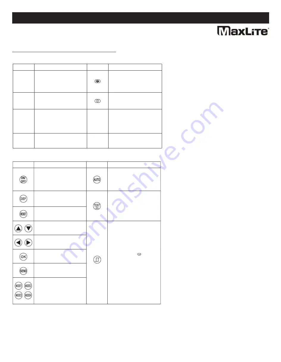
LED Indicators:

Button Operation:


BUTTON

DESCRIPTION

BUTTON

DESCRIPTION

Press the “ON/OFF” button, the

light goes to permanent on or

permanent off mode, and the

sensor is disabled. (MUST press

“Auto” button to quit this mode.)

Display the current/latest setting

parameters in LED indicators (the

LED indicators will turn on for 

showing the setting parameters.)
Press “RESET” button, all settings

go back to settings of dip switch in

sensor
Enter in the setting condition, and 

navigate to up and down for 

choosing selected parameters in 

LED indicators
Navigate to left and right for 

choosing selected parameters in 

LED indicators

Keep records of selected 

parameters in remote control or in 

Mode 1, Mode 2, Mode 3 or Mode 4

Upload the selected parameters

to sensors

4 scene modes with preset

parameters which are available to

be changed and saved in modes

Press “AUTO” button, the sensor 

starts to function and all settings 

remain the same as the latest status 

before the light is switched on/off

The button “TEST” is for testing

sensitivity only. After you choose 

sensitivity thresholds, then you press 

“TEST” button. The sensor goes to 

test mode (hold time is only 2s) 

automatically. Meanwhile the 

stand-by period and daylight sensor 

are disabled. Press “AUTO” button to 

quit from this mode.
Press this button to open or close the 

smart photocell sensor which takes 

the place of a normal photocell 

sensor switch. When remote control 

enters in setting conduction, you can

choose to open and close the smart 

photocell sensor. If the sensor is 

open 2 LED indicators of daylight 

sensor are on. Choosing photocell

sensor setpoint on/off to light and 

stand by time is only      . When the 

natural light level exceeds setpoint 

off to light, the sensor will wait and

monitor for 1 minute in order to 

confirm the natural light level 

increase is not temporary before 

forcing the lights to go off. When the 

nautral light level is lower than 

setpoint to light, the lights will turn on

even when the space is not occupied. 

When natural light level goes lower 

than this setpoint to light, the sensor 

will wait and monitor for 1 minute in 

order to confirm the natural light level

decrese is not temporary before 

forcing the lights to go on.

Operating Instructions                                                                                                           BLHE3 Series

MaxLite BayMax Linear High Bay Eco Series

®

Summary of Contents for BayMax High Bay Eco BLHE3 Series

Page 1: ...trical and grounded connections in accordance with the National Electrical Code and any applicable local code requirements All wiring connections should be capped with UL approved wire connectors CAUT...

Page 2: ...ailable separately Materials Required Figure B 1 One 1 LED fixture BLHE Series Two 2 Metal cables not included 1 As shown in Figure B 2 one end of the sling is buckled and fixed and the other is the r...

Page 3: ...e C 8 8 Lift the fixture to the wall to ensure that each tapping screw passes through the center hole of the mounting bracket Figure C 9 9 Slide the fixture to the position shown in Figure C 10 This w...

Page 4: ...wire to the leading black wire the supply s white common wire to the leading white wire Connect the green wire to ground Operating Instructions BLHE3 Series MaxLite BayMax Linear High Bay Eco Series E...

Page 5: ...ngs of dip switch in sensor Enter in the setting condition and navigate to up and down for choosing selected parameters in LED indicators Navigate to left and right for choosing selected parameters in...

Page 6: ...ENT PERMITTED BY LAW AND IN ANY EVENT SHALL BE LIMITED TO THE WARRANTY PERIOD SPECIFIED ABOVE THE LIABILITY OF MAXLITE SHALL BE LIMITED TO THE TERMS OF THE EXPRESS WARRANTY SET FORTH HEREIN IN NO EVEN...

Page 7: ...rre en conformit avec le code lectrique national et les ventuelles exigences locales applicables du code Toutes les connexions lectriques seront termin es avec des connecteurs pour fils approuv s UL P...

Page 8: ...B Installation c bles c bles disponibles s par ment Mat riel requis Figure B 1 Un 1 luminaire LED s rie BLHE Deux 2 c bles m talliques non fournis 1 Comme illustr dans la Figure B 2 un bout du harnais...

Page 9: ...s marqu s Figure C 8 8 Lever le luminaire au niveau du mur pour s assurer que chaque vis autotaraudeuse passe travers l orifice central du support de montage Figure C 9 9 Faire glisser le luminaire da...

Page 10: ...Sch ma de c blage de l unit de la batterie de secours 1 Utiliser un tournevis pour ouvrir le bo tier de jonction sur le dos du luminaire Enlever l entr e de c ble d sir e 2 Faire passer le conduit tra...

Page 11: ...r les param tres s lectionn s dans voyants LED Enregistrer les param tres s lectionn s dans la t l commande en Mode 1 Mode 2 Mode 3 ou Mode 4 T l verser les param tres s lectionn s dans les capteurs 4...

Page 12: ...D FINIE DANS LES PR SENTES MAXLITE NE SERA EN AUCUN CAS RESPONSABLE DES DOMMAGES PARTICULIERS ACCESSOIRES OU CONS CUTIFS Y COMPRIS SANS S Y LIMITER LES DOMMAGES R SULTANT DE LA PERTE D UTILISATION DE...

Reviews: