Maxford USA Gee Bee Sportster Model

                                                                                                                                                                                                 /  

6.

  Aileron Servos and Ailerons

 – 

a.


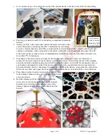
Test fit your aileron servos and prepare the aileron 
servo mounts by using epoxy to attach two servo-
mounting pedestals to each servo hatch cover. 

b.


Test-fit the ailerons to their wing panels, control 
horns and pushrods. (NOTE: If necessary, you 
may reposition the aileron control horns to fit your 
servos; you might need to slice through any Mylar 
covering the precut CA-hinge slots.) 

c.


Use the predrilled holes in each aileron and CA adhesive to attach a control horn to each aileron. Center 
the CA hinges in their slots and use thin CA adhesive to attach the ailerons to their wing panels. 


d.


Mount the aileron servos to the servo hatch covers. 
Attach a 12-inch servo extension to each servo. 
(NOTE: We recommend you also install optional 
Maxford USA servo extension safety clips.)  

e.


Install a servo and attached extension in each wing 
panel by pulling the aileron extensions out through 
the root ribs. Guide the right extension out the hole 
in the top of the right wing panel. Secure the 
aileron servo hatch covers to the wing with 5/16-
inch wood screws. 

f.


Use the Z-bend in the pushrods and supplied EZ 
Connectors to attach the aileron pushrods between 
the aileron control horns and aileron servos. 

7. 

Wing and Mains Gear

 – 

a.


Insert the wing rod half way into either wing 
panel. Slide the remaining wing panel onto the 
wing rod until the root ribs are 2 to 3 inches apart. 

b.


Guide the left aileron’s lead into the root rib of the 
right wing panel and pull it out through the hole in 
the top of the right wing panel. 


(1/4-inch 

squares) 

Page 6 of 12                                                       S121029   Copyright 2012

Summary of Contents for Gee Bee Sportster Model "E"

Page 1: ...eventually destroyed in crashes including one which was flown by Zantford Delbert Granny Granville who was killed in February 1934 attempting to land after an engine failure while trying to avoid peo...

Page 2: ...ck the operation of this model airplane before every flight to ensure that all equipment is still operating correctly and that the model has remained structurally sound Also before every flight check...

Page 3: ...learly mark this RMA on the outside of the package No return or exchange will be authorized after 10 days from the date of your receipt of the product any package delivered to us without a Maxford USA...

Page 4: ...elage Mounted Servos a Using hardware supplied with your servos install the rudder and elevator servos in their servo tray b Connect the EZ Link connectors to the servo arms Guide the EZ Link connecto...

Page 5: ...of rotation If the motor rotated in the clockwise correct direction as viewed from the rear of the airplane return the throttle to minimum disconnect the ESC from the battery switch OFF the transmitt...

Page 6: ...o extension to each servo NOTE We recommend you also install optional Maxford USA servo extension safety clips e Install a servo and attached extension in each wing panel by pulling the aileron extens...

Page 7: ...rt into its opening e Position each fiberglass wheel pant at 90 degrees to the wing then lower the wheel pant over its main gear strut toward the wing s surface f Reposition the wheel pants as necessa...

Page 8: ...d inside their mounting slots in the fuselage NOTE We recommend using a hot soldering iron to cut the Mylar a sharp blade damages wood c Slide the elevator s metal joiner and the horizontal stabilizer...

Page 9: ...heir EZ Link connectors p Connect the aileron s Y cable to your receiver s aileron port Secure the receiver inside the fuselage q Insert the two forward projecting portions of the wing s root ribs int...

Page 10: ...eel pant Drive a 2nd screw into the bottom edge of the root rib wrap the wing wire around the 2nd screw and direct it into and through the wheel pant Drive a 3rd screw into the 3rd rib outboard of the...

Page 11: ...nting plate at the rear of the wing saddle safely set aside the strut mounting screws and bolts for future use Slide the wing to the rear and away from the fuselage and carefully disconnect both ailer...

Page 12: ...your own risk Please enjoy your hobby and fly safely Manufactured by Maxford USA RC Model Mfg Inc Distributed by Maxford USA RC Model Distribution Inc Telephone voice 562 529 3988 15939 Illinois Avenu...

Reviews: