


Copyright Maxford USA 2019
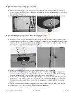
Step 4. Mount the main landing gear assembly
1.
Fix the main landing gear assembly in place by tightening the mounting
down plates as shown. There are holes
the main landing gear.
2.
Slip the main wheels on their axles and use four wheel collars to retain the
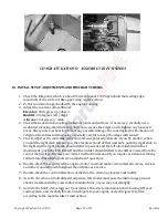
Step5. Assembling the wing and installing the wing flying wires
1.
Install the lower wing center section to the
center section and lower wing panel
slide the Maxlok Pin in posit, mark
into the wing panel Maxlok tab slot after test fit.
2.
Repeat the above step for top wing and
3.
Test fit then install the 6 pcs of the upper wing cabane
section and the fuselage side as shown. There are pre
position of the cabanes. Pay attention to the angle of each of
4.
Connect the upper wing to the lower wing with 4 pcs
bolts and self-lock nuts to connect the wing struts and to mount the
Pay attention to the length of the struts: the rear
strut.
5.
Screws on 4 pcs of the aluminum angle brackets to the
6.
Connect the clevis end of the wires to the connectors as shown.
Page 10 of 13
Step 4. Mount the main landing gear assembly
Fix the main landing gear assembly in place by tightening the mounting screws in the hold
down plates as shown. There are holes pre-drilled in the bottom of the fuselage for mounting
Slip the main wheels on their axles and use four wheel collars to retain the
Step5. Assembling the wing and installing the wing flying wires
Install the lower wing center section to the fuselage; test fit the lower wing
lower wing panels. Test fit Maxlok tab with center section and wing panel,
slide the Maxlok Pin in posit, mark on tab at the edge of the center section, then glue the tab
into the wing panel Maxlok tab slot after test fit.
for top wing and install all Maxflok tabs in position.
the 6 pcs of the upper wing cabane in place on the upper wing’s center
section and the fuselage side as shown. There are pre-drilled holes to locate
position of the cabanes. Pay attention to the angle of each of the cabanes.
Connect the upper wing to the lower wing with 4 pcs of wing struts. Test fit before glue.
lock nuts to connect the wing struts and to mount the flying wire connectors.
Pay attention to the length of the struts: the rear wing strut is longer than the front wing
he aluminum angle brackets to the upper wing and lower wing panels.
Connect the clevis end of the wires to the connectors as shown.
RS190529
screws in the hold-
bottom of the fuselage for mounting
Slip the main wheels on their axles and use four wheel collars to retain the wheels in place.
the lower wing rod through the
Test fit Maxlok tab with center section and wing panel,
at the edge of the center section, then glue the tab
all Maxflok tabs in position.
in place on the upper wing’s center
drilled holes to locate the mounting
Test fit before glue. Use
flying wire connectors.
wing strut is longer than the front wing
upper wing and lower wing panels.