


14
MAXDATA PLATINUM Server 90004R
15
Setting up the system
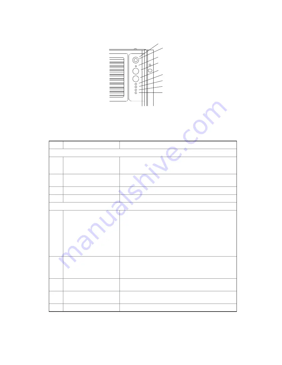
Figure 4 shows the front control panel of the Maxdata Platinum 9000-4R server. The front control
panel of the server displays status lights for fans, hard drives, and power supplies.
�
�
�
�
�
�
�
�
�
Figure 4. Front Panel View
Table 2. Front Panel Control and Indicator Description
Item
Feature
Description
Switches
A
System ID Switch
Toggle switch for blue System ID LEDs (the front panel
system ID LED is located inside the system ID switch). See E
below for description of LED operation.
B
Assert SDINT (System
Diagnostic Interrupt) Switch
Asserts SDINT. This switch is accessible through a small
opening and requires a narrow tool to activate.
C
Reset switch
Resets the system.
D
Power switch
Toggles system power.
LED Indicators
E
System ID (Blinking or
Solid Blue). The system ID
LEDs are located inside the
system ID switch on the
front panel, and on the back
panel.
Identifies the system. The system ID is activated either
by the system ID switch or through server management
software.
Pressing the system ID switch once turns on the LEDs solid
blue
Press the system ID switch again, the solid blue LEDs turn
off
Remove activation - LEDs turn on blinking for 4 minutes
(max). LEDs cannot be turned off by pressing the switch.
F
Main Power (Solid Green,
Blinking Green indicates
the system is in sleep
mode.)
A continuously lit LED indicates the presence of DC power in
the system. The LED goes out when the power is turned off
or the power source is disrupted. Off indicates power off.
G
Power Fault (Solid Amber)
Indicates any system power faults. Off indicates power is
OK.
H
Cooling Fault (Solid Amber)
Indicates any system cooling faults. Off indicates system
cooling is OK.
I
General Fault (Solid amber)
Indicates a system failure. Off indicates system is OK.


