background image

i-32V5H MIDI 

Chiller and Inverter Air/Water heat pumps with axial fan

31

9.3 

SANITARY

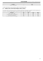
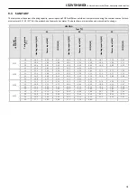
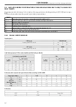
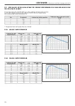
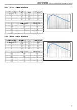
The tables show the values of heating capacity, power input and COP for different outside air temperatures during the summer season fot tech-

nical water at 45 / 50 / 55°C for the production of domestic hot water. The data shown are indicative and may subject to change.

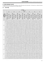
HEATING

Model 


i-32V5H MIDI

T aria esterna


[°C]

Tout [°C]

45

50

55

Heating capacity [kW]

Power input [kW]

COP [W/W]

Heating capacity [kW]

Power input [kW]

COP [W/W]

Heating capacity [kW]

Power input [kW]

COP [W/W]

0121

20

18,9

4,28

4,42

18,4

4,75

3,87

18,1

5,29

3,42

25

18,8

3,85

4,88

18,4

4,30

4,28

18,0

4,80

3,75

30

20,4

3,85

5,30

19,9

4,29

4,64

19,3

4,80

4,02

35

21,6

3,82

5,65

21,1

4,31

4,90

-

-

-

0126

20

23,6

5,50

4,29

23,1

6,08

3,80

22,7

6,75

3,36

25

22,4

4,68

4,79

22,0

5,30

4,15

21,5

5,77

3,73

30

24,2

4,66

5,19

23,6

5,25

4,50

23,0

5,89

3,90

35

25,8

4,73

5,45

25,1

5,24

4,79

-

-

-

0128

20

22,5

5,12

4,39

22,1

5,62

3,93

21,6

6,26

3,45

25

19,8

4,19

4,73

19,4

4,62

4,20

18,9

5,15

3,67

30

21,1

4,05

5,21

20,6

4,54

4,54

20,2

5,07

3,98

35

22,1

3,93

5,62

21,7

4,44

4,89

-1,0

-1,00

-1,00

0132

20

25,3

5,74

4,41

24,8

6,36

3,90

24,2

7,03

3,44

25

24,6

5,09

4,83

24,1

5,66

4,26

23,7

6,39

3,71

30

26,5

5,06

5,24

25,9

5,74

4,51

25,2

6,35

3,97

35

27,7

4,95

5,60

27,1

5,59

4,85

-

-

-

Summary of Contents for i-32V5H MIDI 0121

Page 1: ...ical specifications provided in this manual It is besides forbidden the reproduction under any form of the texts of the figures contained in this manual This manual is a translation from the official...

Page 2: ...er and Inverter Air Water heat pumps with axial fan 2 00 01 2021 EM AR First emission Rev Date Compiled Approved Note Code Serie BTE01040101001 00_i 32V5 Midi_EN Chiller and Inverter Air Water heat pu...

Page 3: ...il of connections and location 12 3 1 3 Weights 12 3 1 4 Location of the centre of gravity and vibrations dampers 12 3 2 TECHNICAL SERVICE AREAS 13 3 3 HYDRAULIC CIRCUIT 15 3 3 1 System water specific...

Page 4: ...BLE 27 9 PERFORMANCE TABLES 29 9 1 HEATING 29 9 2 COOLING 30 9 3 SANITARY 31 9 4 DATA FOR ENERGY CERTIFICATION OF BUILDINGS ACCORDING TO UNI TS 11300 4 FOR HEAT PUMPS 32 9 4 1 Model i 32V5H MIDI 0121...

Page 5: ...s allows a low value of pressure losses on the air side and therefore the possibility of using fans with a low number of revolutions with a consequent reduction in machine noise On request the coils c...

Page 6: ...CER AF 1 AXIAL FAN PSH 1 HIGH PRESSURE SWITCH RD DELIVERY LIVE HKA 1 HEAT EXCHANGER ANTIFREEZE RESISTOR RL LIQUID LINE TE SD 1 SUCTION TEMPERATURE PROBE RS SUCTION LINE TE DT 1 EXHAUST TEMPERATURE PRO...

Page 7: ...perature probes compressor thermal protection fan thermal protection flow switch on the water side to protect the evaporator high pressure switch 1 9 HYDRAULIC CYRCUIT The units in the series are supp...

Page 8: ...lver Line anti corrosion treatment x x Electronic expansion valve x x Electronic circulator x x Water side safety valve x x Flow switch indication of flow presence x x Y filter x x Domestic hot water...

Page 9: ...at exchanger which is activated when the temperature of the water inside the ex changer falls below 4 C For BT units this value must be set according to the percentage of glycol in the system and the...

Page 10: ...is particularly suitable during night operation Below are the decreases in capacity and sound power level when the fan silent mode function is active The reduction refers to the test condition 3 of th...

Page 11: ...temperature detection replicating the functionality of the on board control 3 INSTALLATION All handling installation and maintenance operations must be carried out by QUALIFIED PERSONNEL only Before...

Page 12: ...Shipping weight kg Weight in service kg 0121 250 240 0126 250 240 0128 265 255 0132 265 255 3 1 4 Location of the centre of gravity and vibrations dampers The position of the centre of gravity of eac...

Page 13: ...ice potential sources of danger The installation site of the unit must be free from foliage dust etc which could block or cover the heat exchange coils Installation should be avoided in areas subject...

Page 14: ...ions in locations with strong winds refer to the area classification according to the Beaufort scale If the value is 7 strong wind average wind speed 13 9 17 1 m s it is strictly necessary to keep the...

Page 15: ...an 1 mm obligatory to maintain the validity of the guarantee Charging unit and discharge valve where necessary CAUTION When dimensioning the pipes make sure that the maximum system side leakage is not...

Page 16: ...hardness 4 5 8 5 dH Temperature 65 C Oxygen content 0 1 ppm Max quantity glycol 40 Phosphates PO4 2ppm Manganese Mn 0 05 ppm Iron Fe 0 3 ppm Alkalinity HCO3 70 300 ppm Chlorine ions Cl 50 ppm Sulphat...

Page 17: ...I HEAT PUMP WITH DESUPERHEATER 5 Hi T2 REMOTE CONTROLLER 2 VDIS3 DIVERTER VALVE 6 SAS SANITARY PROBE 3 CADDY WATER STORAGE WITH DOMESTIC HOT WA TER EXCHANGER 7 FANCOIL TERMINALS 4 PUFFROLLER TECHNICAL...

Page 18: ...water content it must be ensured that the pipes connecting to the unit have sufficient capacity to com pensate for this difference The additional volume required is shown in the table Model i 32V5H M...

Page 19: ...k on In any case it is advisable to use an external tap to fill the system B A If the unit must be completely drained first close the manual inlet and outlet shutters not supplied and then disconnect...

Page 20: ...pe R32 R32 R32 R32 Refrigerant quantity 7 kg 4 3 4 3 5 1 5 1 Refrigerant quantity in ton of CO2 equivalent 7 ton 2 90 2 90 3 44 3 44 Design pressure high low mod heat pump bar 42 8 1 3 42 8 1 3 42 8 1...

Page 21: ...EATER The performance with desuperheater is shown under conditions 1 of the technical data table for water outlet temperatures of 45 C and 55 C from the desuperheater Model i 32V5H Midi Tout DS 45 C T...

Page 22: ...l The correction factor for water flow rate shall be calculated to maintain the same temperature difference as would be obtained without the use of glycol The pressure drop correction factor is applie...

Page 23: ...a function of altitude are calculated for cooling under the conditions 1 and for heating under the conditions 3 in the above technical data tables and are given for altitudes of 500 1000 1500 and 2000...

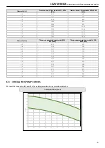
Page 24: ...orking points shown below Flow rate m l s Useful head p models 0121 0126 kPa Useful head p model 0128 0132 kPa 0 5 107 4 111 2 0 6 103 5 108 7 0 7 98 6 105 5 0 8 92 7 101 5 0 9 85 8 96 7 1 0 78 0 91 2...

Page 25: ...rate l s Three way pressure drops models 0121 0126 kPa Three way pressure drops models 0128 0132 kPa 0 5 0 75 0 75 0 6 1 08 1 08 0 7 1 47 1 47 0 8 1 92 1 92 0 9 2 43 2 43 1 0 3 00 3 00 1 1 3 62 3 62 1...

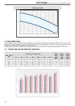
Page 26: ...metric method The sound pressure values are calculated from the sound power level using ISO 3744 2010 considering units operating in the open area 7 1 POWER AND SOUND PRESSURE STANDARD Model i 32V5H M...

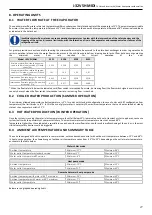
Page 27: ...t when the flow switch intervention low rate i ncreasing flow is reached 8 2 CHILLER WATER PRODUCTION SUMMER OPERATION The minimum allowed evaporator outlet temperature is 5 C for units with standard...

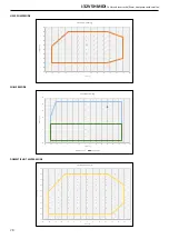
Page 28: ...10 5 0 5 10 15 20 25 30 35 40 Tacqua C Taria C Envelope heating CHILLER MODE 10 5 0 5 10 15 20 25 20 15 10 5 0 5 10 15 20 25 30 35 40 45 50 55 Tacqua C Taria C Envelope cooling Cooling Cooling BT DOM...

Page 29: ...1 8 00 3 01 15 25 5 3 74 6 82 25 0 4 34 5 76 24 6 4 95 4 97 24 1 5 52 4 37 24 4 6 11 3 99 24 0 6 78 3 54 23 5 7 56 3 11 20 24 8 3 24 7 65 24 3 3 79 6 41 23 9 4 38 5 46 23 4 4 99 4 69 23 6 5 50 4 29 23...

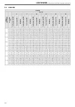
Page 30: ...4 04 5 45 23 9 4 11 5 82 35 17 7 6 00 2 95 18 7 6 19 3 02 20 6 6 32 3 26 21 9 5 35 4 09 24 0 5 47 4 39 26 2 5 56 4 71 40 16 5 6 60 2 50 17 5 6 75 2 59 19 3 6 90 2 80 20 7 5 90 3 51 22 6 6 02 3 75 24...

Page 31: ...21 20 18 9 4 28 4 42 18 4 4 75 3 87 18 1 5 29 3 42 25 18 8 3 85 4 88 18 4 4 30 4 28 18 0 4 80 3 75 30 20 4 3 85 5 30 19 9 4 29 4 64 19 3 4 80 4 02 35 21 6 3 82 5 65 21 1 4 31 4 90 0126 20 23 6 5 50 4...

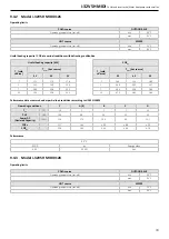
Page 32: ...the heat pump referred to nominal conditions DC COPPL COP della pompa di calore nelle condizioni di parzializzazione definite dalla norma UNI EN 14825 9 4 1 Model i 32V5H MIDI 0121 Operating limits C...

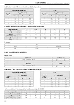
Page 33: ...5 45 55 7 17 3 17 3 17 0 7 2 44 2 14 1 80 2 24 1 24 0 23 4 2 3 49 2 92 2 37 7 26 0 25 8 25 1 7 4 04 3 28 2 64 12 25 3 25 0 24 1 12 4 70 3 83 2 64 Performance data measured under partial load condition...

Page 34: ...68 4 26 5 39 7 06 COPDC 2 42 2 62 3 82 4 41 5 27 Performances 35 C SCOP s Energy class 4 29 169 A 9 4 4 Model i 32V5H MIDI 0132 Operating limits COLD source OUTDOOR AIR Operating temperature cut off...

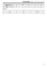
Page 35: ...MIDI Chiller and Inverter Air Water heat pumps with axial fan 35 Operating conditions F A E B C D COPPL 2 29 2 57 3 94 5 03 6 96 COPDC 2 34 2 53 3 54 4 09 4 90 Performances 35 C SCOP s Energy class 4...

Page 36: ...by water flow rate at full load 9 5 1 Model i 32V5H MIDI 0121 Outside air dry bulb temperature C Charge factor F EER Cooling capacity kW 35 100 3 00 17 7 30 75 4 03 12 9 25 50 4 89 8 8 20 25 5 14 9 5...

Page 37: ...30 40 50 60 70 80 90 100 EER F C Charge factor F EER 20 C xC 0 95 20 6 15 0 94 15 6 09 0 87 10 5 63 0 71 5 4 60 0 46 2 2 98 0 29 1 1 88 9 5 4 Model i 32V5H MIDI 0132 Outside air dry bulb temperature...

Page 38: ...ange and or suc on the work environments Advice for safe use Do not breath in fumes or aerosol Storage Close carefully and store in a cool dry and well ven lated area Keep in original containers Incom...

Page 39: ...i 32V5H MIDI Chiller and Inverter Air Water heat pumps with axial fan 39...

Page 40: ...ADVANTIX SpA Via S Giuseppe Lavoratore 24 37040 Arcole VR Italy Tel 39 045 76 36 585 E mail info advantixspa it www maxa it...

Reviews: