


i-32V5H MIDI
Chiller and Inverter Air/Water heat pumps with axial fan
27
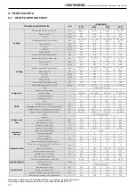
8. OPERATING LIMITS
8.1
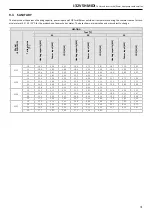
WATER FLOW RATE AT THE EVAPORATOR
The nominal water flow rate refers to a temperature difference between the inlet and outlet of the evaporator of 5°C. The maximum permissible
flow rate is the one with a temperature difference of 3°C and the minimum is the one with a temperature difference of 8°C at nominal conditions
as indicated in the data sheet
Insufficient water flow rate can cause evaporation temperatures too low with the intervention of the safety devices and the
stopping of the unit and, in some limit cases, with the formation of ice in the evaporator and consequent seious failures of the
refrigertion circuit.
For greater precision we enclose a table showing the minimum flow rates to be ensured to the plate heat exchanger in order to guarantee its
correct operation (please note: the water flow switch prevents the anti-freeze probe from tripping due to lack of flow,but does not guarantee
the
minimum
water
flow
rate
required
for
correct
operation
of
the
unit)
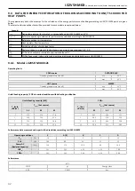
Model i-32V5H Midi
0121
0126
0128
0132
Minimum water flow rate to be guaran
-
teed in chiller mode (condition (1) data
sheet) [l/s]
0,529
0,558
0,723
0,776
Maximum water flow rate to be guaran
-
teed in chiller mode (condition (1) data
sheet) [l/s]
1,41
1,49
1,93
2,07
Intervention flow rate status – flow switch
decreasing* [l/s]
0,445
0,445
0,528
0,528
Intervention flow rate status – flow switch
increasing* [l/s]
0,477
0,477
0,588
0,588
* When the flow rate falls below the indicated limit (flow switch intervention flow rate - decreasing flow) the flow switch signals an alarm,which
can only be reset when the flow switch intervention low rate -i ncreasing flow - is reached.
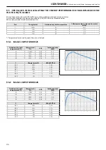
8.2 CHILLER WATER PRODUCTION (SUMMER OPERATION)
The minimum allowed evaporator outlet temperature is 5°C for units with standard configuration In case of units with BT configuration (low
temperature) the limit drops to -8°C. In this the use of glycol water is necessary.The maximum temperature that can be manteined at steady
state at the evaporator outlet is 22°C.
8.3 HOT WATER PRODUCTION (WINTER OPERATION)
Once the system is running the water inlet temperature must not fall below 20°C: lower value not due to transient or start-up phases, can cause
system faults with the possibility of compressor failure, The maximum water outlet temperature must not exceed 60°C.
Temperature higher than those indicated, especially in conjcution with water flow rates, could result in malfunctioning of the unit, or in the most
critical cases safety devices could be triggered.
8.4
AMBIENT AIR TEMPERATURE AND SUMMARY TABLE
The unit are designed anf built to operate in summer mode, with condensation control, with outdoor air temperature between -15°C and 48°C.
In heat pump operation, the allowed range of outdoor air temperature varies from -20°C to 35°C depending on the outlet water temperature,
as shown in the table below.
Water chiller mode
Ambient temperature
Minimum -15°C
Maximum 48°C
Water outlet temperature standard version
Minimum 5°C
Maximum 22°C
Water outlet temperature BT version
Minimum -8°C
Maximum 22°C
Heat pump mode
Ambient temperature
Minimum -20°C
Maximum 35°C
Water outlet temperature
Minimum 25°C
Maximum 60°C
Domestic hot water heat pump mode
Ambient temperaure with water at 44°C maximum
Minimum -20°C
Maximum 40°C
Ambient temperature with water at 60°C maximum
Minimum -7°C
Maximum 26°C
Water outlet temperature
Minimum 25°C
Maximum 60°C
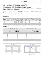
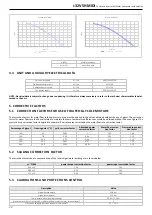
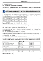
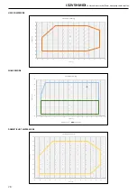
Below are the graphed operating limits.